|
Special Hobby 1/48 I.M.A.M. Ro.57bis Long Range Fighter/Ground Attack by Paolo Carli |

 |

Click the STORMO! Eagle to return to the Gallery |
|
This airplane was designed in 1939 and remained in the prototype stage for a long time, despite the airplane's good performance in test flights.
However, in 1942, under the pressure of the war, it was finally decided to build a small number of these airplanes. Unfortunately, by this time,
the airplane was outmoded and proved unsatisfactory in service; inline and radial engines were already generating 1,500 hp such as the DB.605
and Piaggio P.XII RC 35 (the Ro.57's radials provided 840 hp). The Ro.57 would have been supplanted by the much more advanced and powerful
Ro.58 in 1943. |

|

|
|
|
|
Today I present my new work on a plane that has always fascinated me for its clean and tapered lines, the Ro 57!
The kit is the
Special Hobby in 1/48 - 48075 and unfortunately nothing aftermarket, even if in the box there is a nice plate of photoengraving:
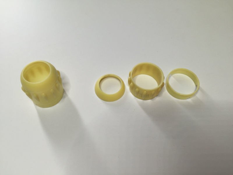
The subject is Ro.57 bis, Red-9 probably belonging to 1o Reparto Sperimentale at Ciampino sud in the first months of 1943. As my custom, the kit will be heavily modified and for this project I will use the nomenclatore and the use and maintenance booklet. Here I present some photos on the changes I am making to the model. My aim is to open the engine compartment and upgrade the cockpit. Let's start with the cockpit. The seat proposed by the kit must be modified as indicated in the manual nomenclatore: 

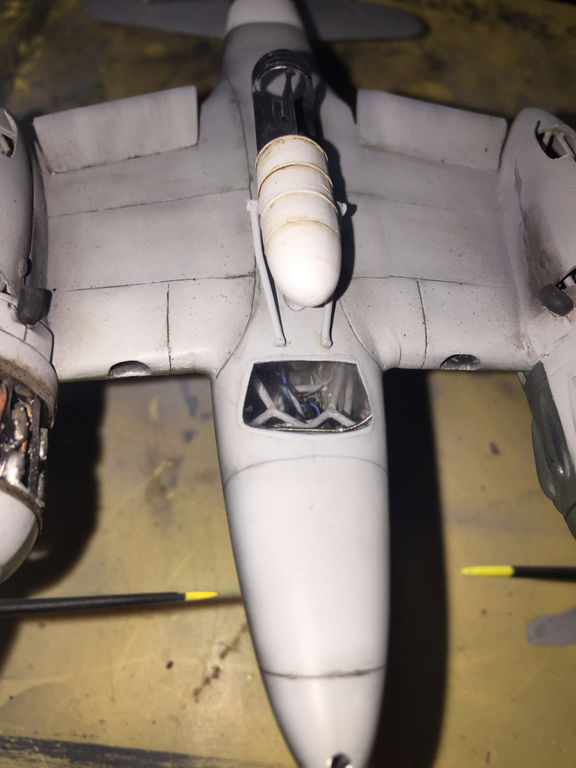
The aircraft has a large window in the lower fuselage that shows everything inside so you have to arm yourself with patience and detail the cockpit floor, the rear part of the instrument panel and recreate the tubular structure of the frame. In addition, the tank and the weapons compartment that are fixed between the front truss should also be recreated ... even here the use of the nomenclature is essential. 


Rear instrument panel:
Structure: 


Now the final photos with all the inserts and colored elements ... the tank has been completely self-built in scratch and the weapons have been modified:


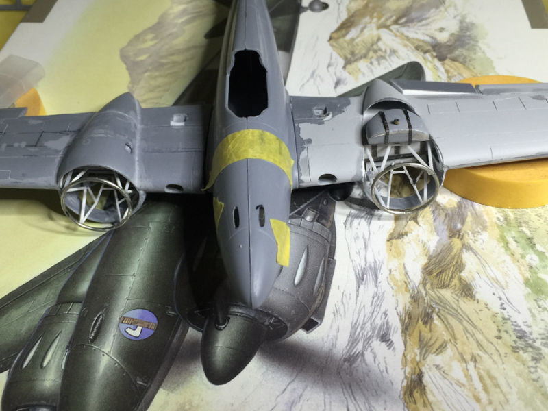
Here I did a lot of work and I had the "unhealthy" idea of wanting to expose the radial engine, the Fiat AR 74, to make the subject prettier in my eyes. I wrote an "unhealthy" because I realized that using the paneling of the kit as reference points for the structures to be built, I didn't end up with the technical drawings of the plane. Basically the reference lines of the kit do not correspond to the underlying structures and consequently all the interior furnishings that I wanted to recreate are incorrect in the position, I will talk about it shortly to make you understand what I mean ...: The works carried out are many: - separation of the various elements of the engine nacelle - creation of the oil tank - created and lowered the flaps - created and placed in open position the slats - created the engine instrument panels - detailed the compartments of the trolleys - detailed the inside of the flaps of the naca (I'm considering whether to open them) - started adding the various pipes All these things I have to replicate also in the other wing as from under the trolley compartment you can see all these structures, therefore: - created the second engine mount - created the second oil tank (I tried to make it the same as the other) Of course it won't be as detailed as the other builds but it is wasting me a lot of time because these works were not planned. Now the photos:
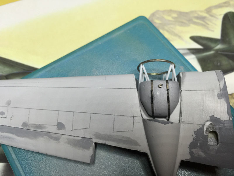
I have tried to detail the various parts that make up the engine hood and thinning the magni ring to transparency: 

the oil tank is only sketchy:
Flap separation and gondola cut for tank display:
And here the first problems with the paneling of the kit:
 
In the highlighted area there should be the wing caisson where in the upper portion a part of the trellis of the engine mount would be constrained while the remaining part should be constrained to the carriage support. Here are some pictures to take a look at.
Here the plan drawing of the wing where it is possible to appreciate the arrangement of the structures from above:
So, here in the drawing (taken from the nomenclator manual) you can see the position of the main oil tank and engine mount structures which is bound to the wing box above and to the trolley structure below:
In this other photo (I do not remember the origin) you can see the arrangement from above of the structures in question, note the space behind the tank and the one in front before reaching the flaps. Here the original (Fig.38):
And here how it would be in the kit:
Now the wing of my model:
In order to position the oil tank correctly as per the original drawings I should put it in this position ...
... but the dividing line of the gondola and, theoretically, where it passes under the caisson, is half a centimeter ahead. I verified that if I use the technical drawing of the wing plant as a reference, all the problems I have are solved immediately, also comparing with the only real photo on the location of the oil tank I noticed that the rear nacelle is separated from the front one. oblique and not straight as I did ... moral: - I delete the panels on the wings to redo them as per the technical drawing - lower the air outlet holes of the radiators first I plastered the original panels and closed the oil cooler hole:
Then I re-engraved the panels in the new location, keeping faith with the original technical drawing of the wing:
The engine mount ring is too big and I need to do it again: 

As you can see now the tank is perfectly positioned (it is not finished and it is not glued). As a last step I proceeded to redo both the engine mount and the support ring which were not correct: 


As I wrote at the beginning of the wip, unfortunately from under the trolley compartment you can see the entire front structure so I had to replicate everything including the oil tank ...


Well after having solved the problem of the paneling the work progressed much faster! First I added some reinforcements where the wing contacts the fuselage to make it more solid:
Checked everything with a dry assembly ...
Prepare the flaps: 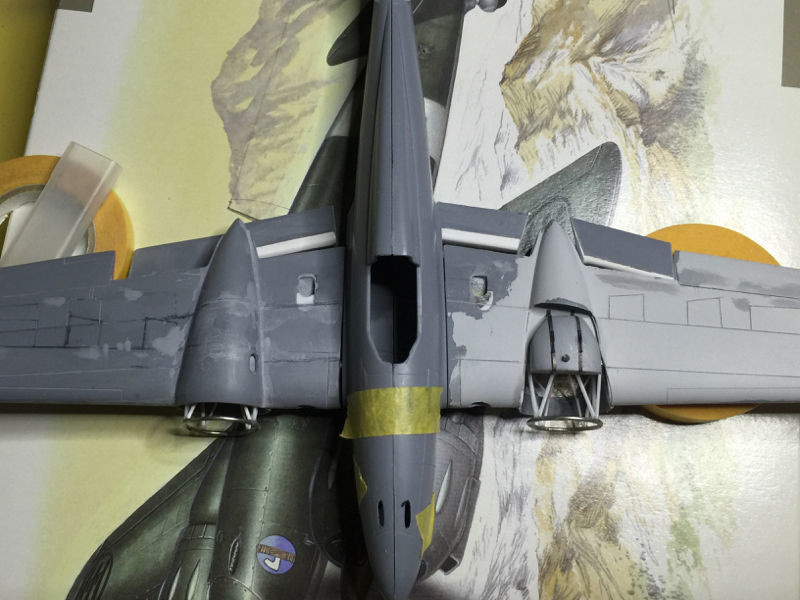

Made the cutouts for the slats: 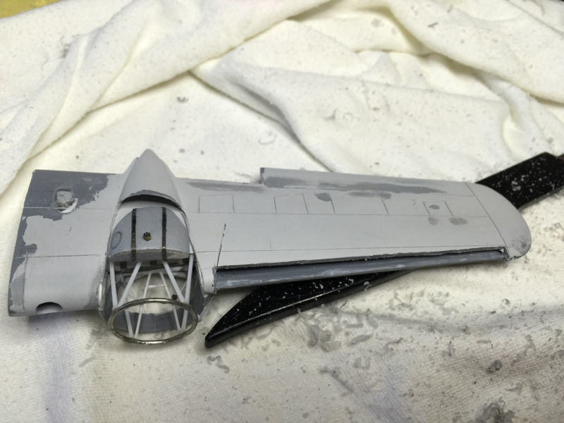


The tail wheel was worked by hollowing out the inside of the fairing and then adding the wheel: 

Thin the plastic of the landing gear closing doors: 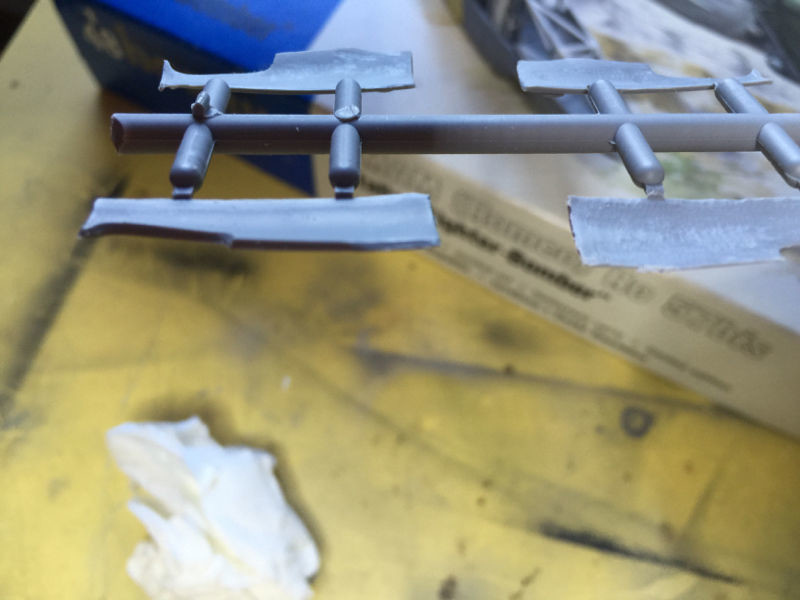

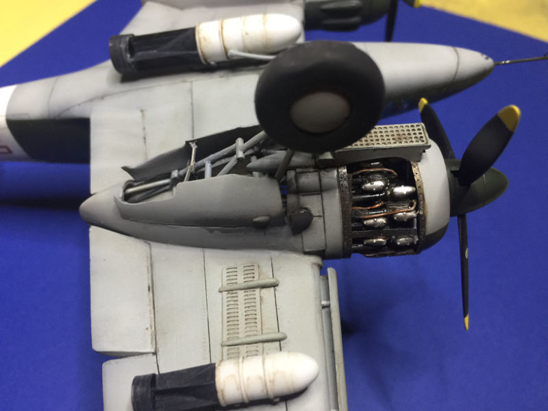
Prepared the engines, the on that's visible I also built the rear part: 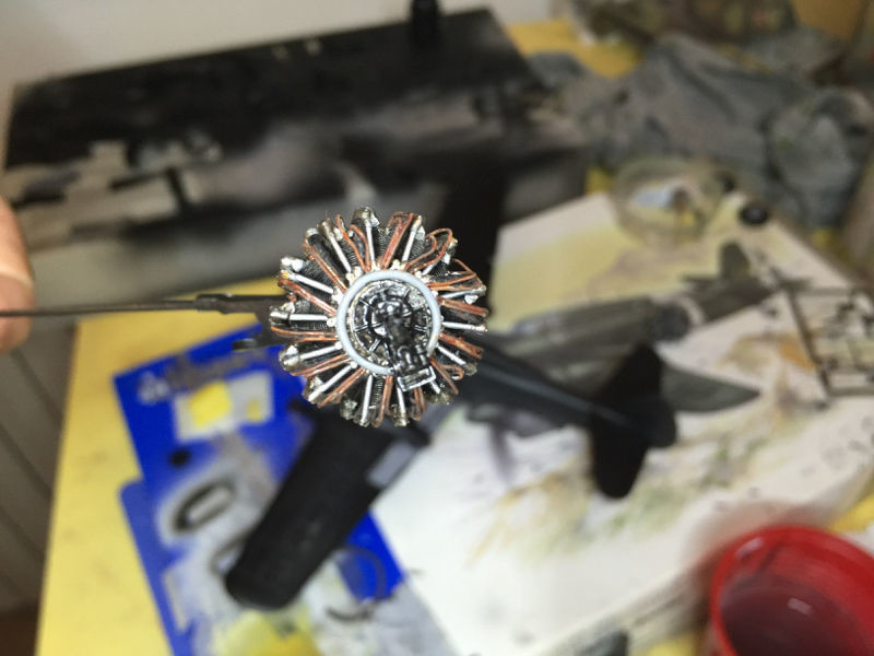

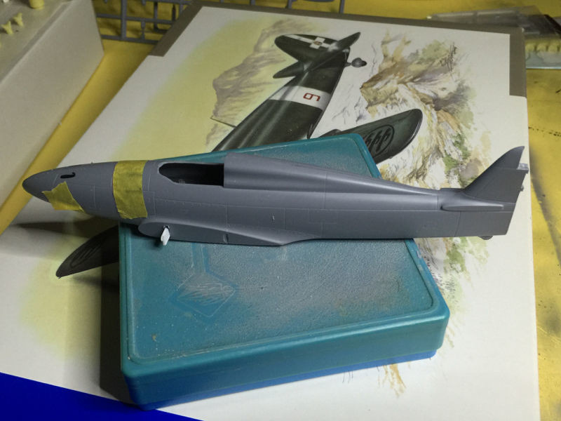
After assembling everything I moved on to the primer and the numerous corrections made with the putty: 

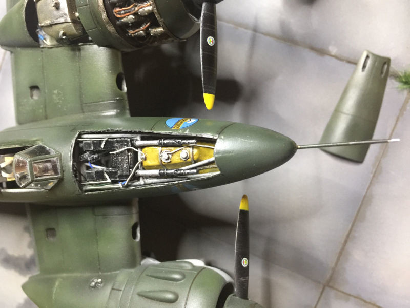
Now I am almost ready to apply the livery which will be in two colors: dark olive green for the upper surfaces and light blue gray for the lower ones. The livery was quite simple to do and since the plane was only used for testing I didn't do much weathering imagining a non-intensive use of the vehicle. I wanted to create a minimal base by adding a driver borrowed from the SM 79. Hope you like it. I also separated the transparent roof but once done I realized that the part that slides backwards on the fuselage is narrower than the same so it is not possible to position it open:
Canopy in the closed-position:
Canopy in the open-position:


The under surfaces: 


And the final photos of the plane in a diaorama setting: 


|
|
|
Aircraft: Meridionali Ro 57 Manufacturer: S.A. Industrie Meccaniche & Aeronautiche Meridionali (I.M.A.M.) Type: Fighter/Bomber Year: 1939 Engine: Two Fiat A.74 RC 38, 14-cylinder radial, air-cooled, 840 hp each Wingspan: 41 ft (12.50 m) Length: 28 ft 11 in (8.80 m) Height: 9 ft 6 in (2.90 m) Weight: 8,950 lb (4,055 kg) (Loaded) Maximum Speed: 320 mph (516 km/h) at 17,200 ft (5,250 m) Ceiling: 30,500 ft (9,300 m) Range: 746 miles (1,200 km) Armament: 2 machine guns 12.7mm (0.5in); 2 x 20mm canons, 2,000 lb (1,500 kg) bomb Crew: 1 |


|
|
|
|
|
|
|
|
|
|
 Ro 57 bis, 1/48 - SO48075")

|


|
|
|
|
November, 2022 STORMO! © 2022 |