|
Italeri 1/48 Aermacchi MB.326M Atlas Impala Mk. I by Vince Tassone  |
|
|
|

Click the STORMO! Eagle to return to the Gallery |
|
There were 762 of these aircraft built that saw service in some ten countries and were produced under licence in
Australia, South Africa and Brazil. This is the story of MB.326, the most successful trainer and light tactical aircraft of the 1960's and 1970's,
and some are still in use today. The project was started in the mid-50s, when there was debate within N.A.T.O. about the standardization of training methods in the air forces of member-countries. From the immediate post-war years, Macchi had worked on the design and production of an aircraft for this specific use, first with the construction under licence of the Fokker S.11 Instructor in 1950, (the aircraft took on the name of Macchi 416), then with the production of the MB.323 in 1952. It was decided to produce a trainer powered by a jet engine and the project was drawn-up and presented officially in March 1954. It outlined a two-seat jet-propelled aircraft with the two crew members seated in tandem, designed for basic flying instruction. After an examination of the design which lasted more than eighteen months, the programme was approved by the Ministry late in 1955 and Macchi received an order to construct three prototypes. The first of these made its maiden flight, flown by chief test-pilot Guido Carestiato, on December 10, 1957 and the second flew the following year. After the tests and trials, in November 1958 the prototypes were transferred to the Pratica di Mare experimental squadron, for a series of operational flights. A month later there was an order for the construction of four more models, considered as pre-production aircraft. This period lasted until 1960 when, sure of having a viable and efficient aircraft at its disposal, the Aeronautica Militare placed an order for 100 production aircraft. The first training course with the MB.326 started in March 1962.[1]
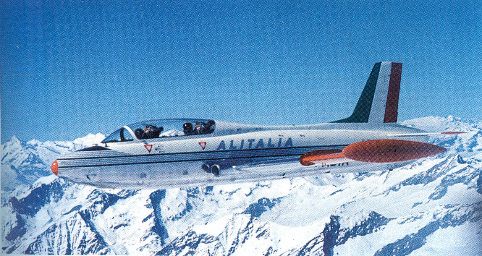
Confident with the success on the national market, Macchi launched a huge promotional campaign in search of export markets. However, the first of these was the national airline Alitalia, which in February 1963 set up a civil flying school using the small Macchi trainer. As a result, four aircraft designated MB.326D were completed, with modified instrumentation and navigation systems and radio-assistance similar to that used by airlines. Two years later there came an order of eight MB.326s from Tunisia, having first tested a B version with fixed armament (2 machine-guns) and a bomb- load of 880 pounds (400 kg) on four wing mountings. Ghana then bought nine MB.326Fs, which were like those of the previous variant but with more sophisticated avionics and a larger fuel capacity. In 1965 Macchi had its first major success: commercial agreements were drawn up with South Africa and Australia to start the production under licence of the MB.326. South Africa chose the M version (which had been improved and modified compared with earlier models), to the tune of 300 aircraft, 64 of which were to be bought directly. Australia decided to build 73, (with an option on 33) of the MB.326 H version, with updated instrumentation and navigation aids and a more powerful engine. Twelve aircraft were to be bought in Italy, and the remainder built under licence by the Commonwealth Aircraft Corporation.[1]
The next version (appearing in the spring of 1967) was the MB.326G, with a Viper turbojet producing a thrust of 3,390 pounds (1,540 kg) and a considerable increase in the type of external weapons carried. Argentina ordered 12 aircraft of the GB sub-series with simplified avionics, and then Brazil showed interest. In particular the Forca Aerea Brasileira requested 112 MB.326s to be built under licence in the Embraer works, and these aircraft were redesignated AT-26 Xavante. There followed orders from Zaire (17 aircraft) and Zambia (a further 18).[1] The last production version was the MB.326K, which made its maiden flight on August 22, 1970: this was a single-seat variant and although it was designed for operational training, it could also be used in tactical support roles and the South African Air Force (SAAF) would do just that. It aroused the interest of several African countries, as well as Dubai and the Persian Gulf Emirates, as did the two-seat version, MB.326L. Among the many category records set by the MB.326, the major ones include the altitude record of 56,807 feet (17,315 m) on March 18, 1966.[1] In South African Use: South Africa obtained a license to produce the MB.326M named the Impala Mk.I in 1964 with production starting in 1966. Initially, 40 Italian-built aircraft were received, followed by about 125 locally manufactured by the Atlas Aircraft Corporation for training and in the armed configuration. The Impala Mk.II, a single seater MB.326K featured a South African ECM suite and a host of weapons fits including two 30mm DEFA canons in underwing pods, two 0.5in gun pods, rockets and a 4,000lb payload began production in 1974. The South African Defence Force (SADF) / South African Air Force (SAAF) used Impalas during campaigns against the People's Armed Forces for the Liberation of Angola (FAPLA) and Cuban troops from 1975 to 1989, flying low-level at speeds of 550–650 km/h to evade defenses. During this conflict, only a single Impala was shot down. The Impala was used operationally on 10 June 1980 in Operation Scpetic, the largest anti-SWAPO (South-West Africa People's Organization) sweep during the South African Border War. At 08h00 the SAAF consisting of Mirages, Buccaneers and Impalas Mk.I and II attacked targets at "Smokeshell", "Mulola" and "Ondova" which would become the targets of ground forces later in that afternoon. The Impala offered advantages over more costly jets, being able to operate from rudimentary airfields and deliver quick strikes and were well liked by its crews. It could carry various ordnance six 120 kg bombs or four 250 kg bombs along with 68mm SNEB rocket launchers and two 30mm autocannons or 0.5in gun pods in various attack-configurations. By the 1970s and 1980s, six SAAF squadrons were equipped with the Impala Mk.II. The Impala Mk.II also served as an interceptor, notably shooting down six Mi-8 and Mi-24 helicopters during engagements in 1985. This took place during a pivotal phase of the ground war against Angolan and Cuban forces, which ultimately struggled with supply issues. The aircraft were effective at extreme ranges flying low to avoid enemy MiGs and returning quickly after attacks. The Silver Falcons aerobatic team was equipped with Impala Mk.Is and the Flying Training School at Langebaanweg trained pilots on this aircraft. Operational squadrons included 4, 5, 6, 7, and 8, with the 85 Combat Flying School also using Impalas.
References [1] Angelucci E. and P. Matricardi, "World Aircraft - World War II - Part I", Sampson Low, Bershire House, UK, 1978 [2] Apostolo, G., "Aermacchi MB 326", No. 13, La Bancarella Aeronautica, Torino, Italy, 1999 Ali d'Italia 13, Aermacchi MB.326 
| |||||||||||||||
|
|
|
|
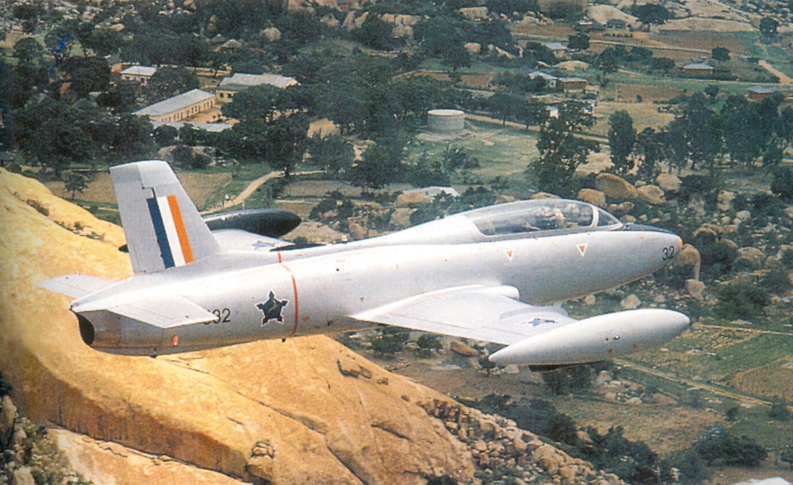
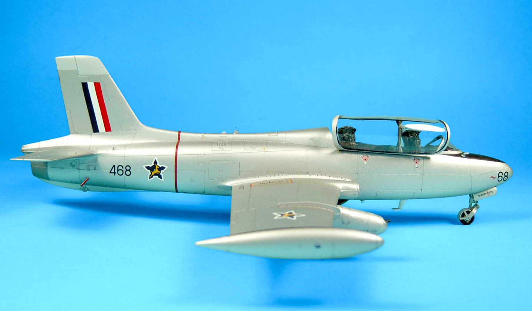
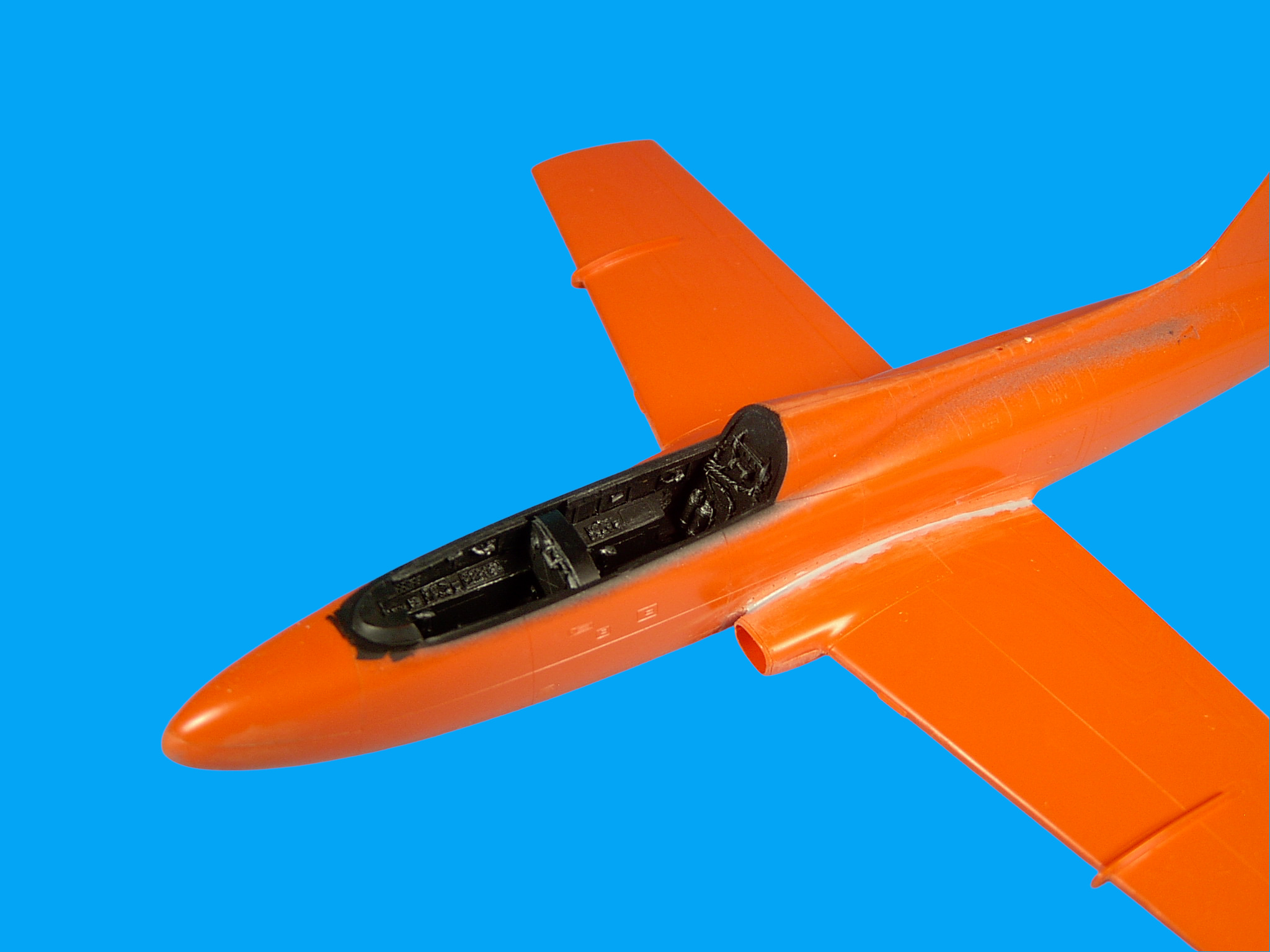
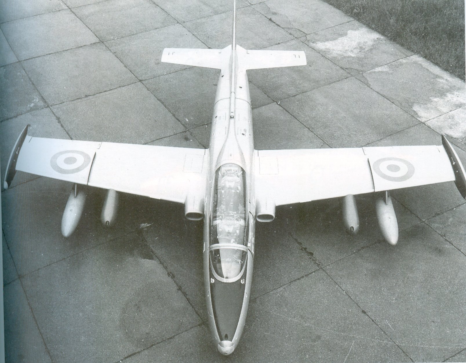
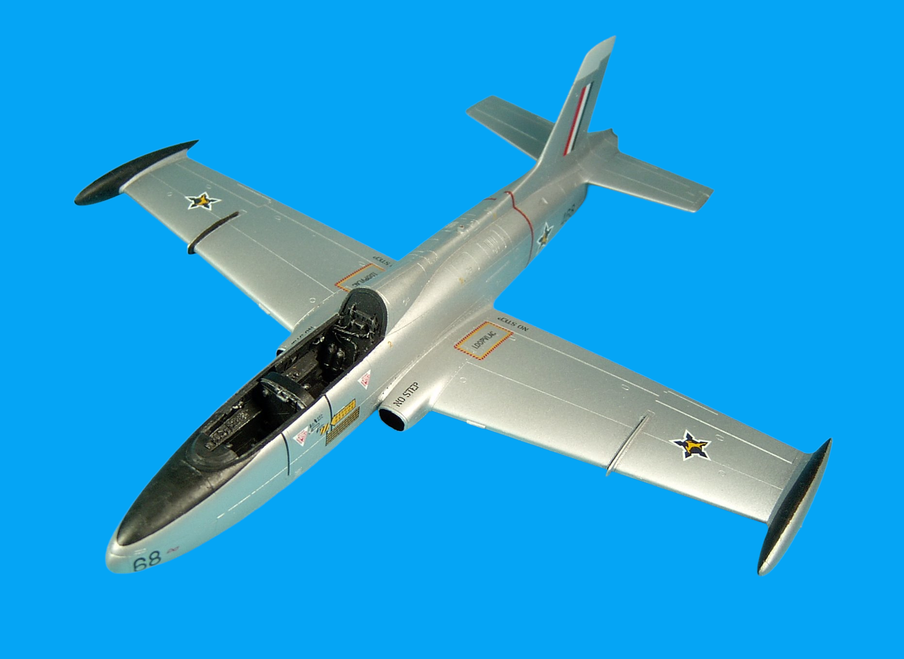
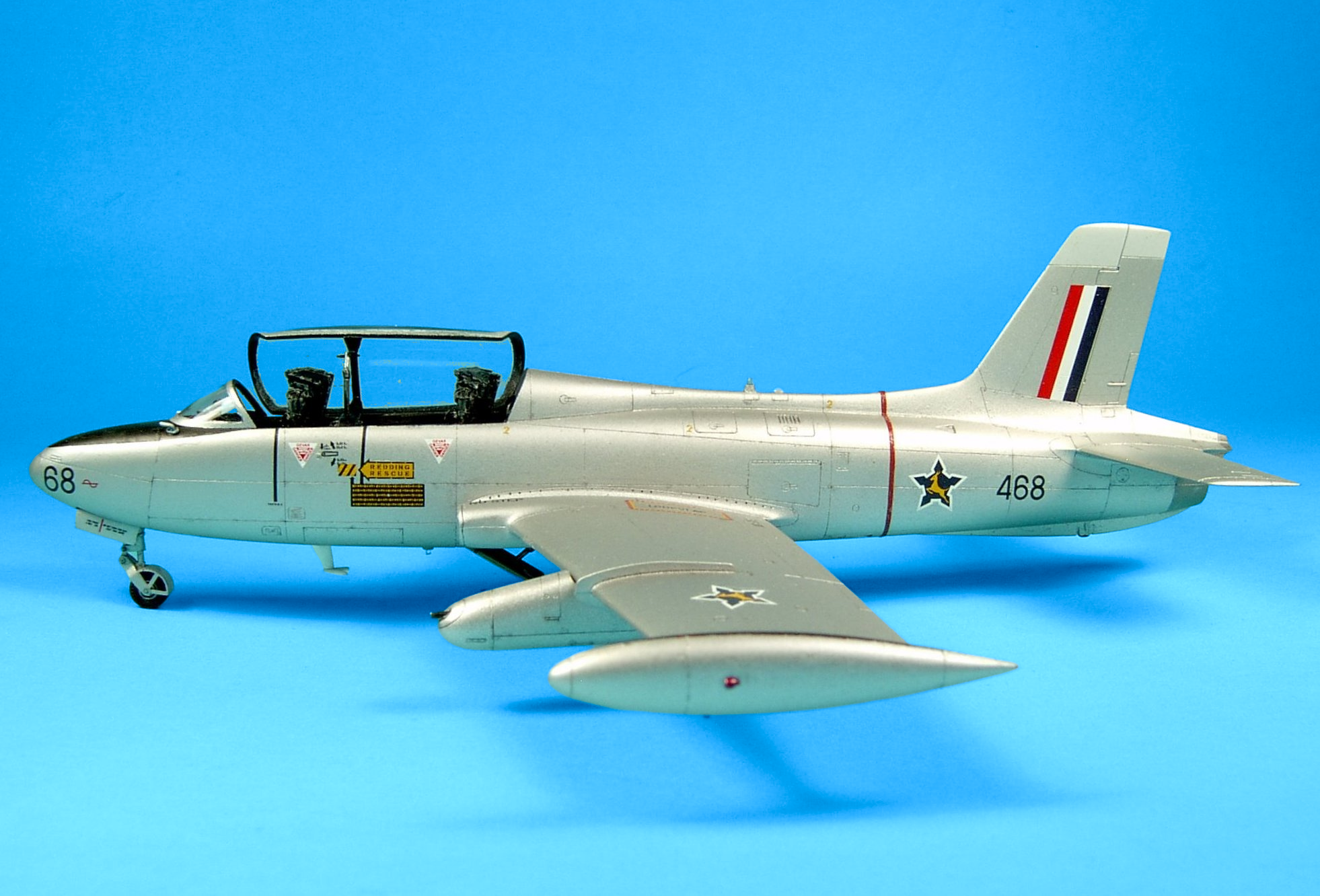
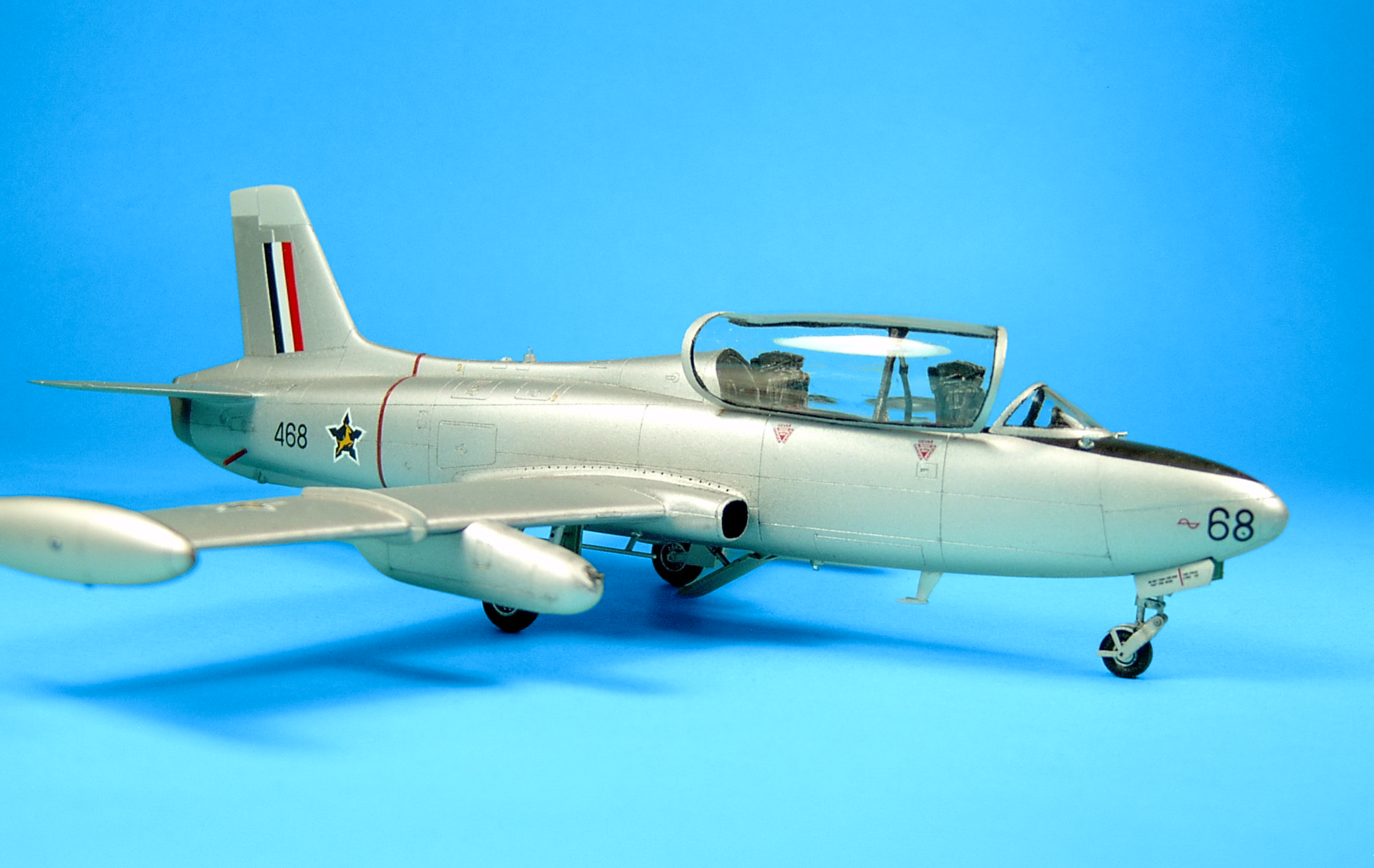
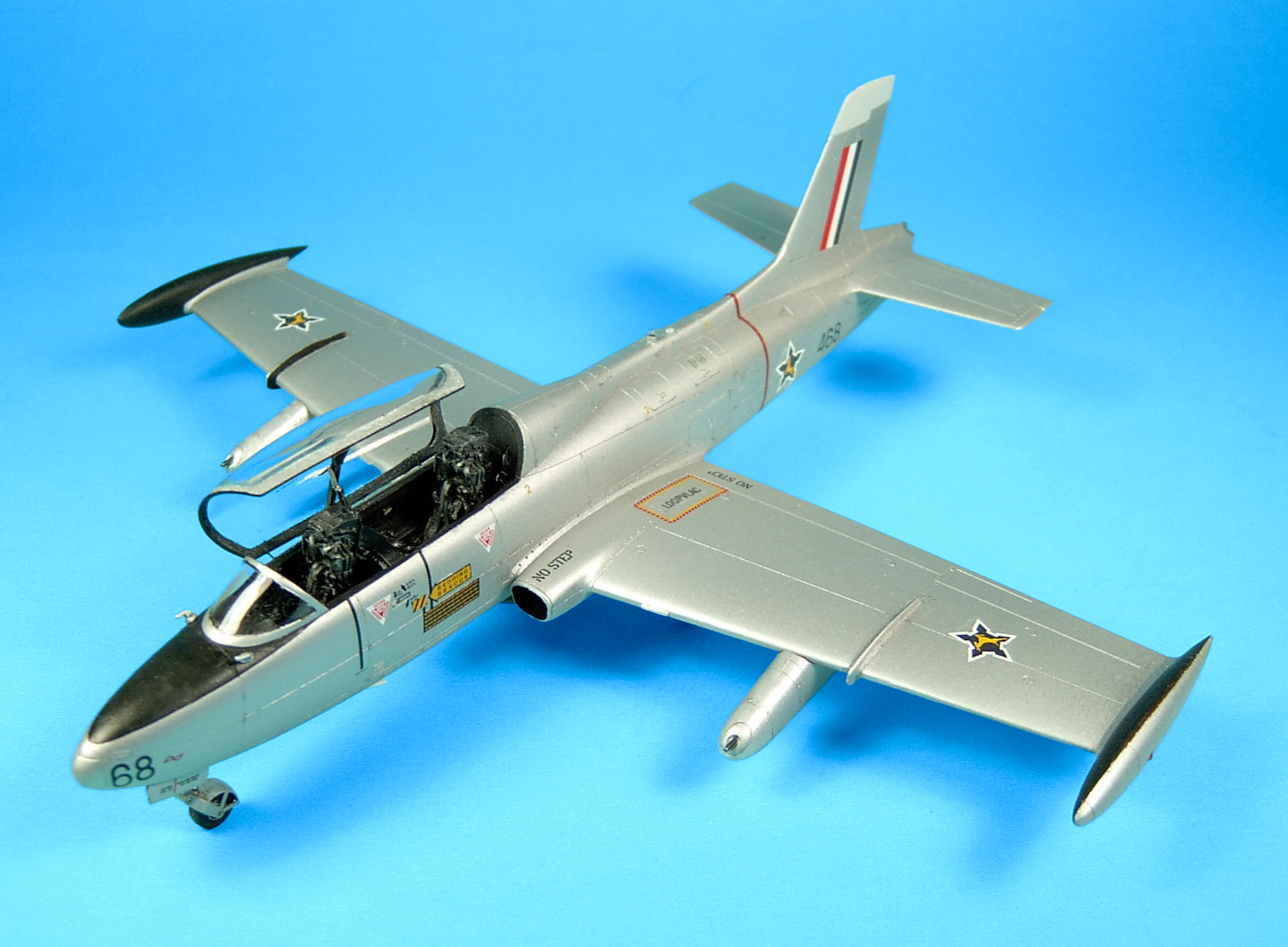
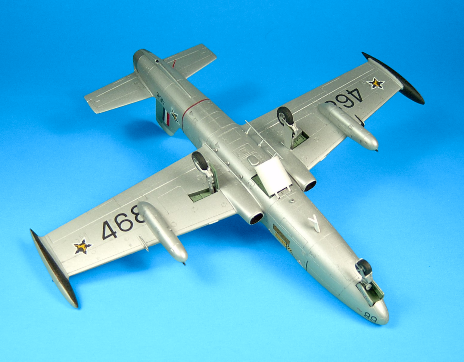
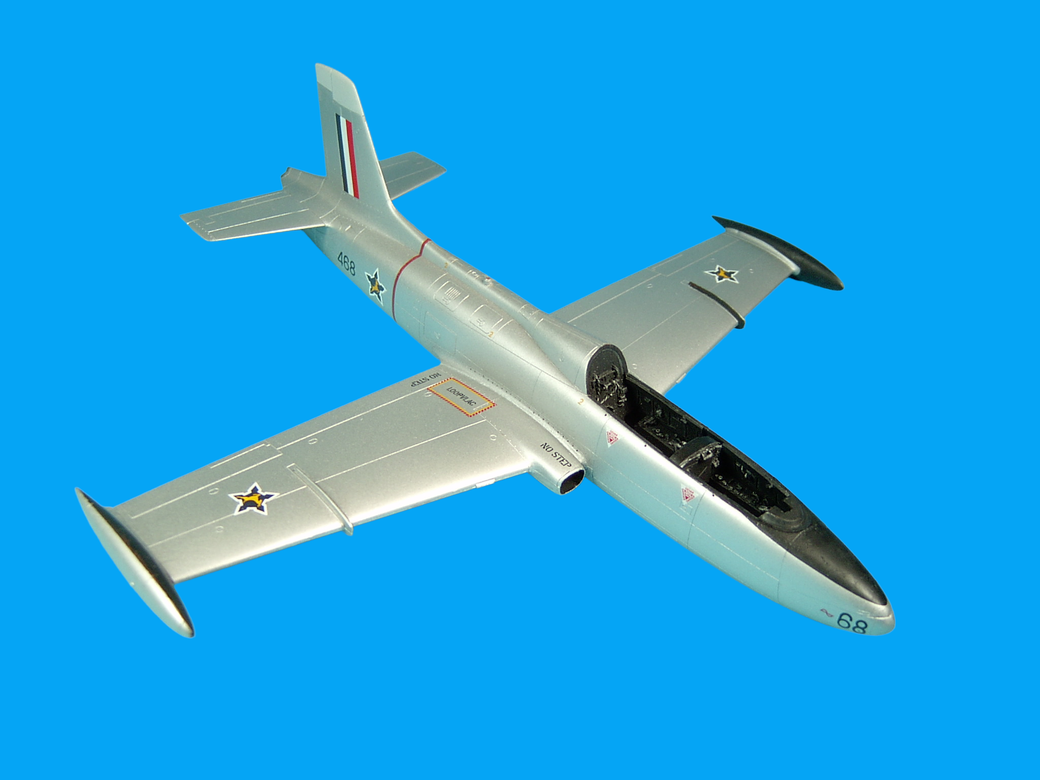
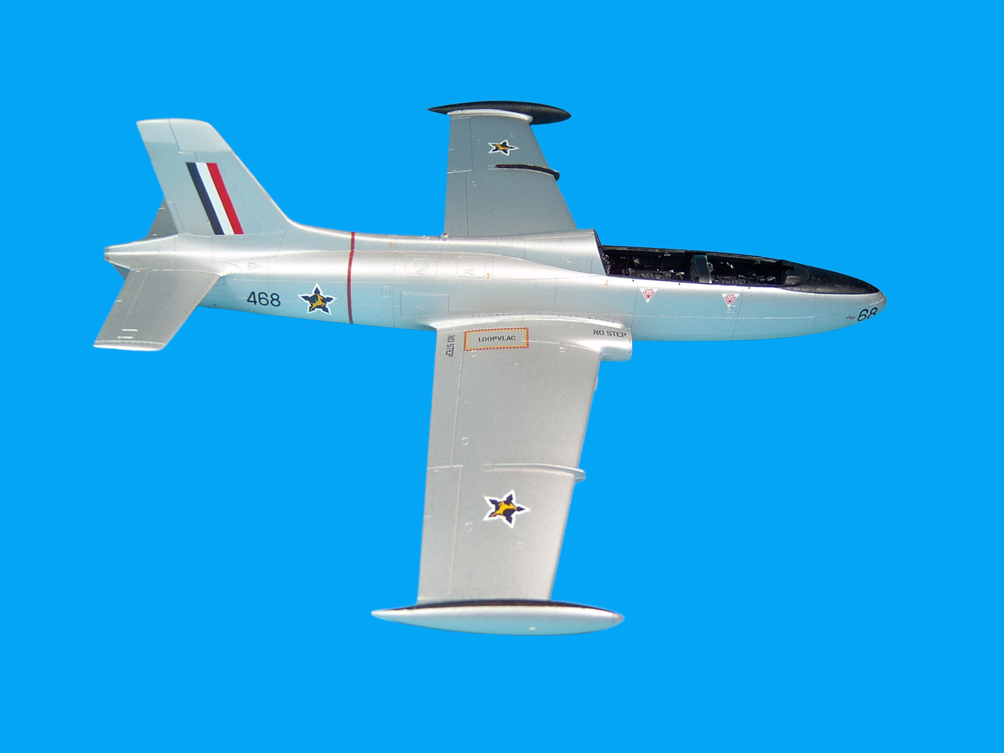
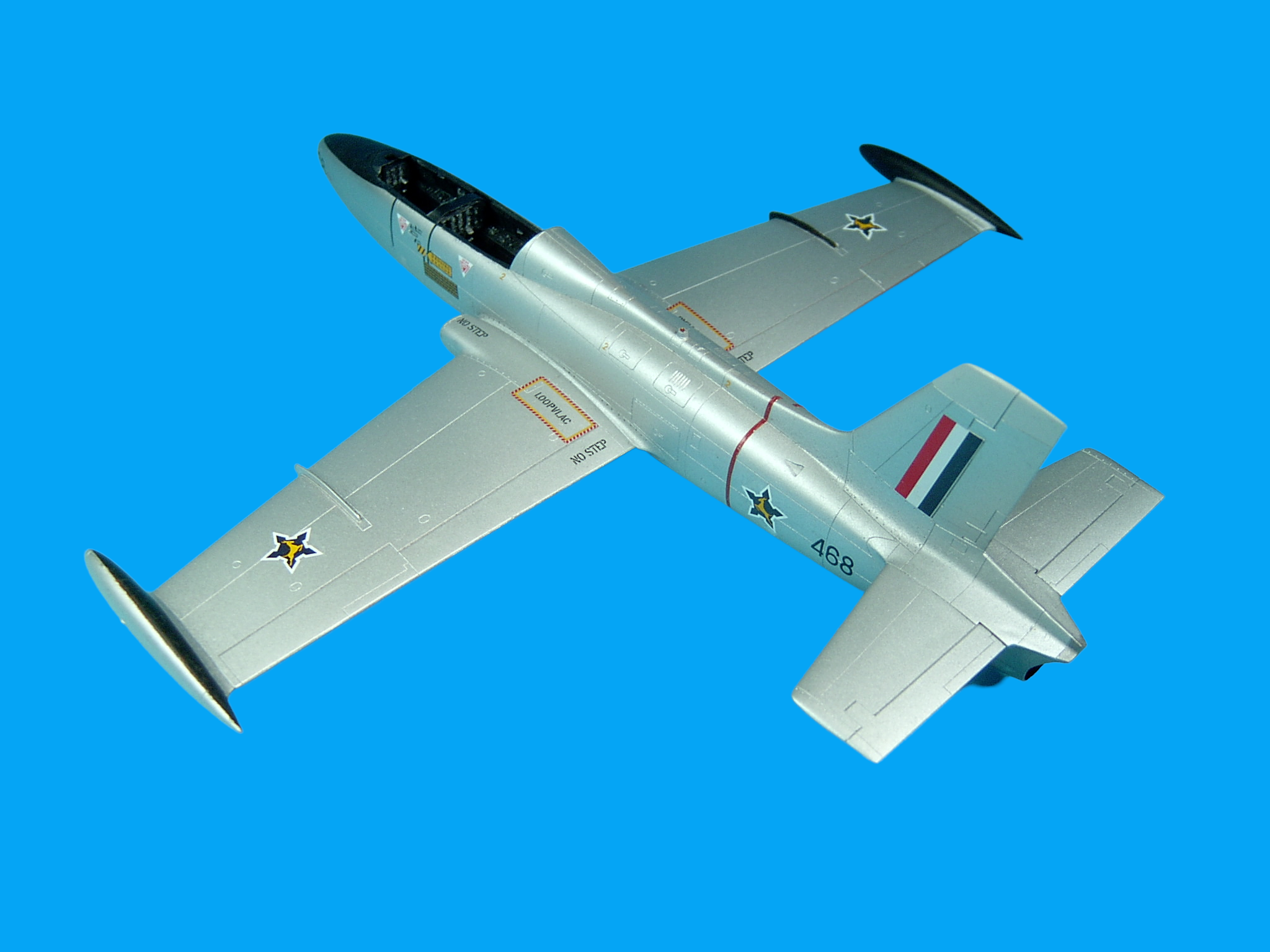
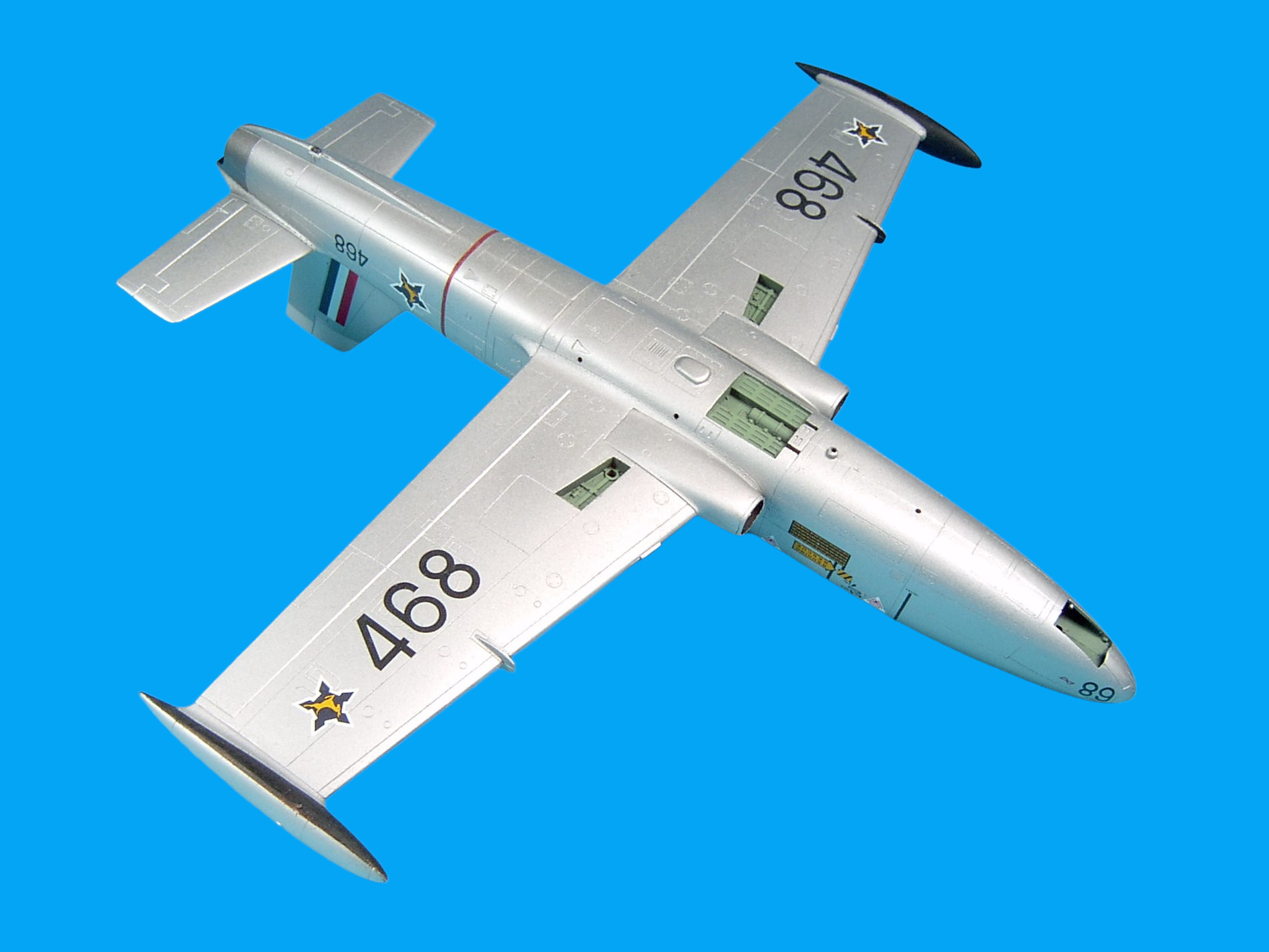
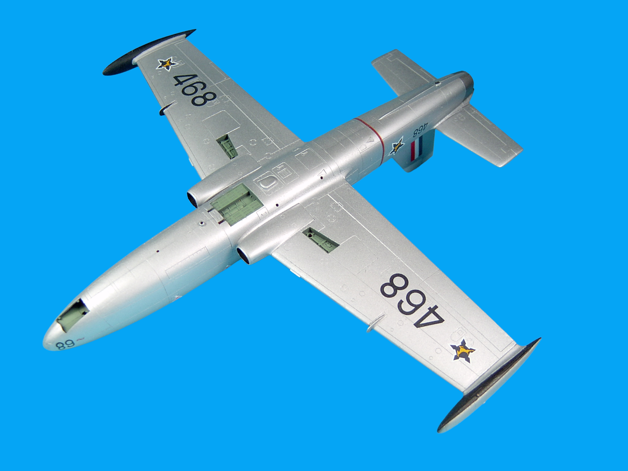
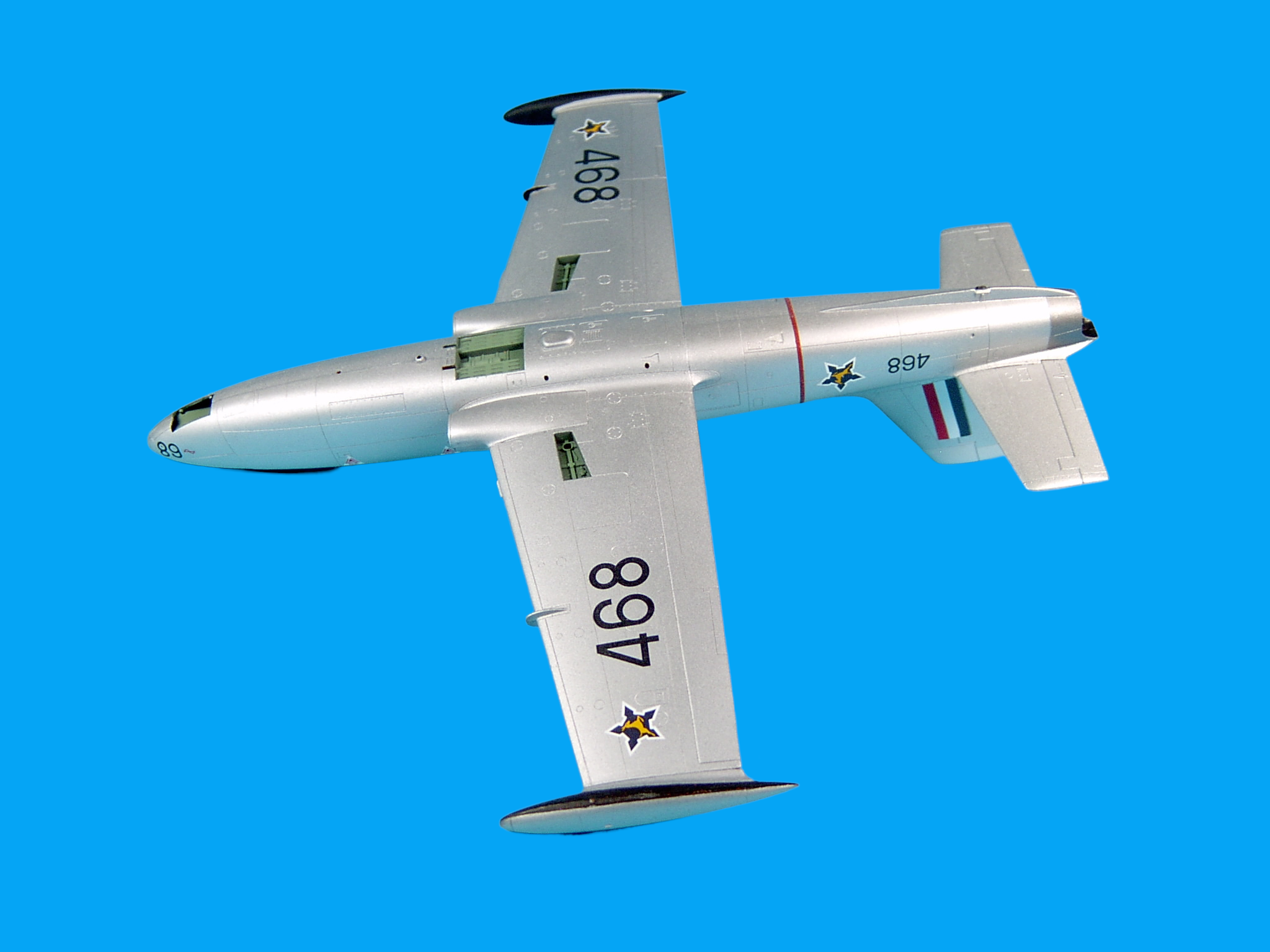
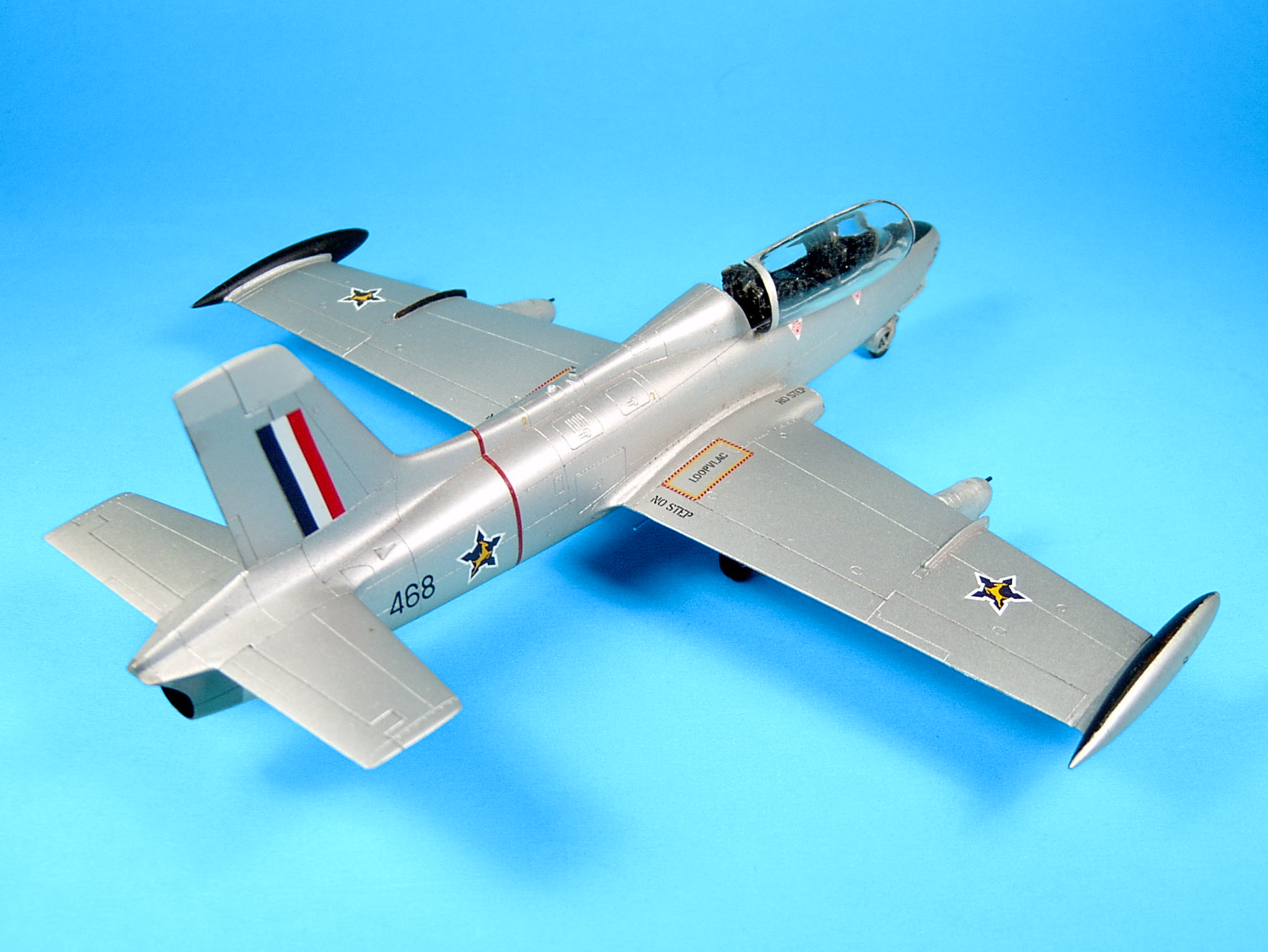
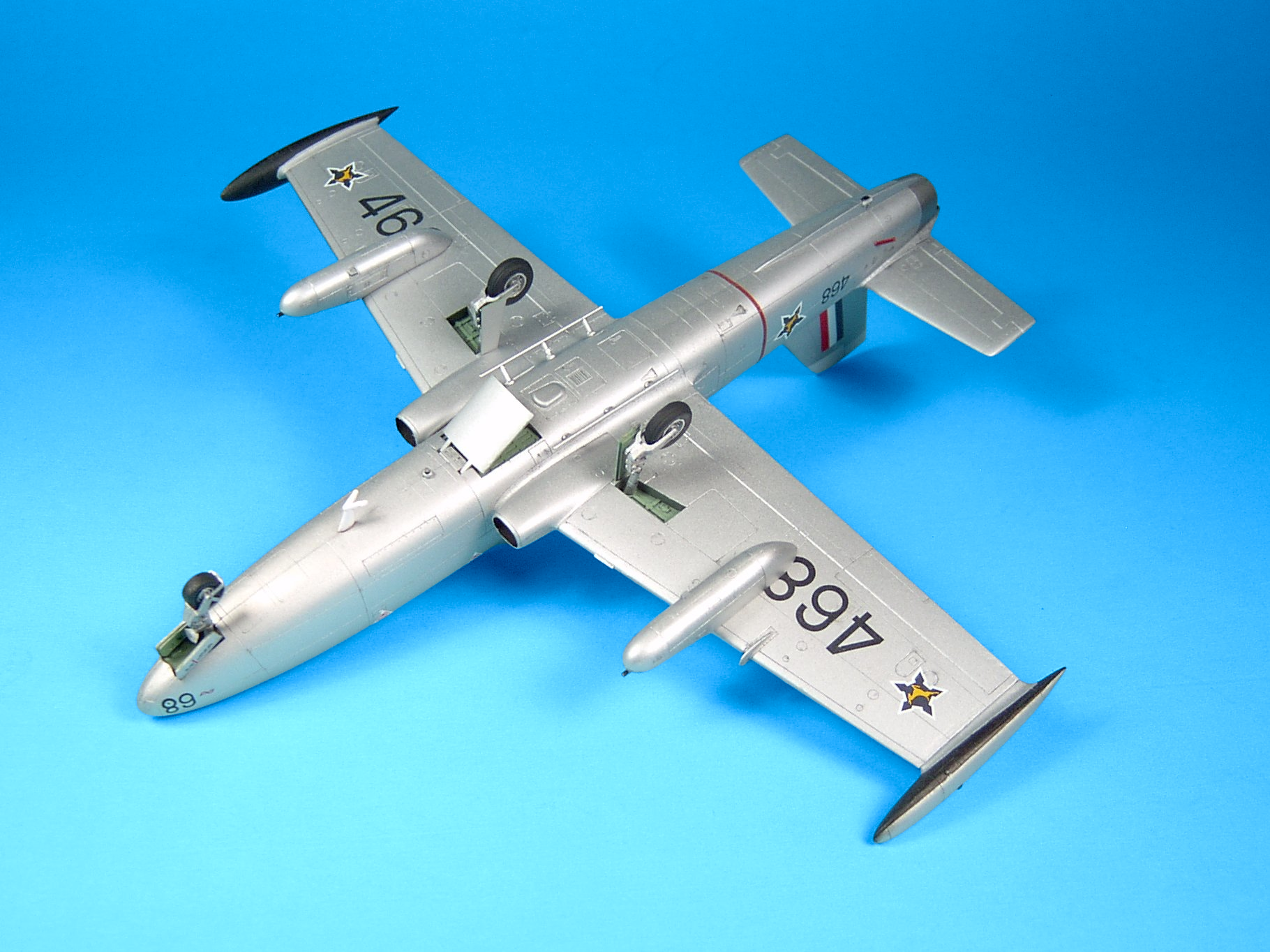
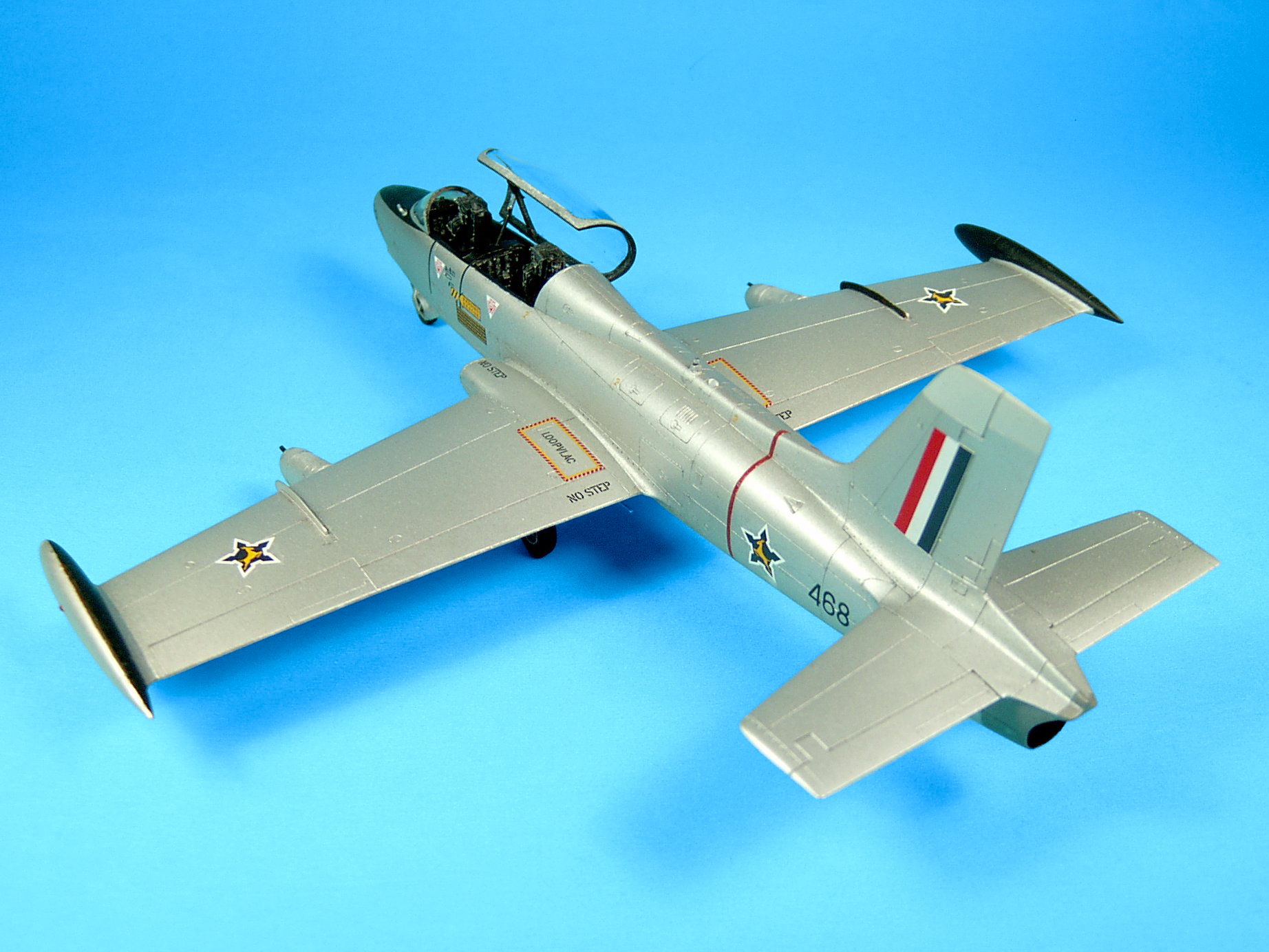
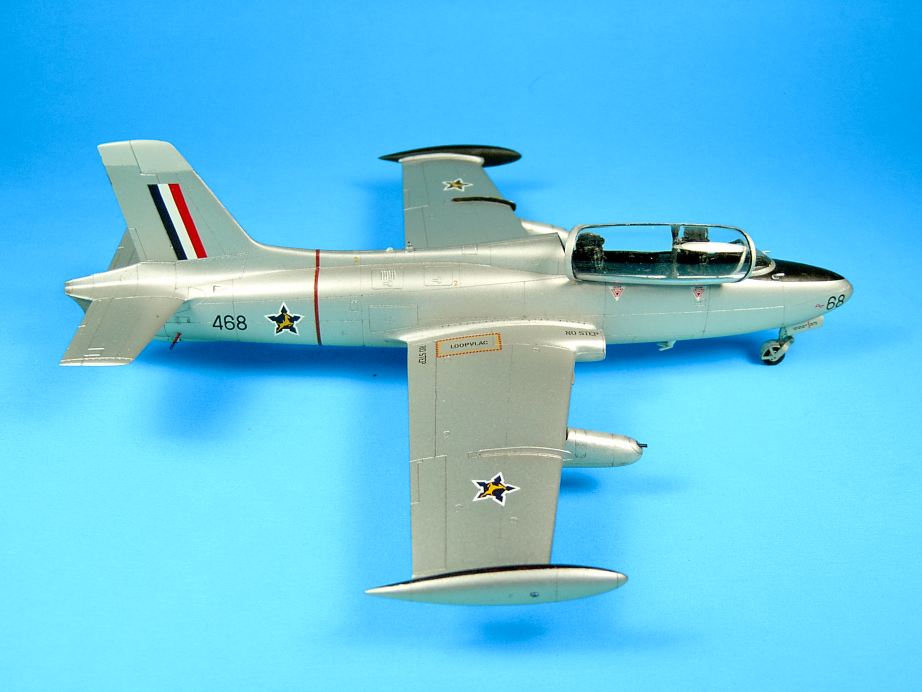
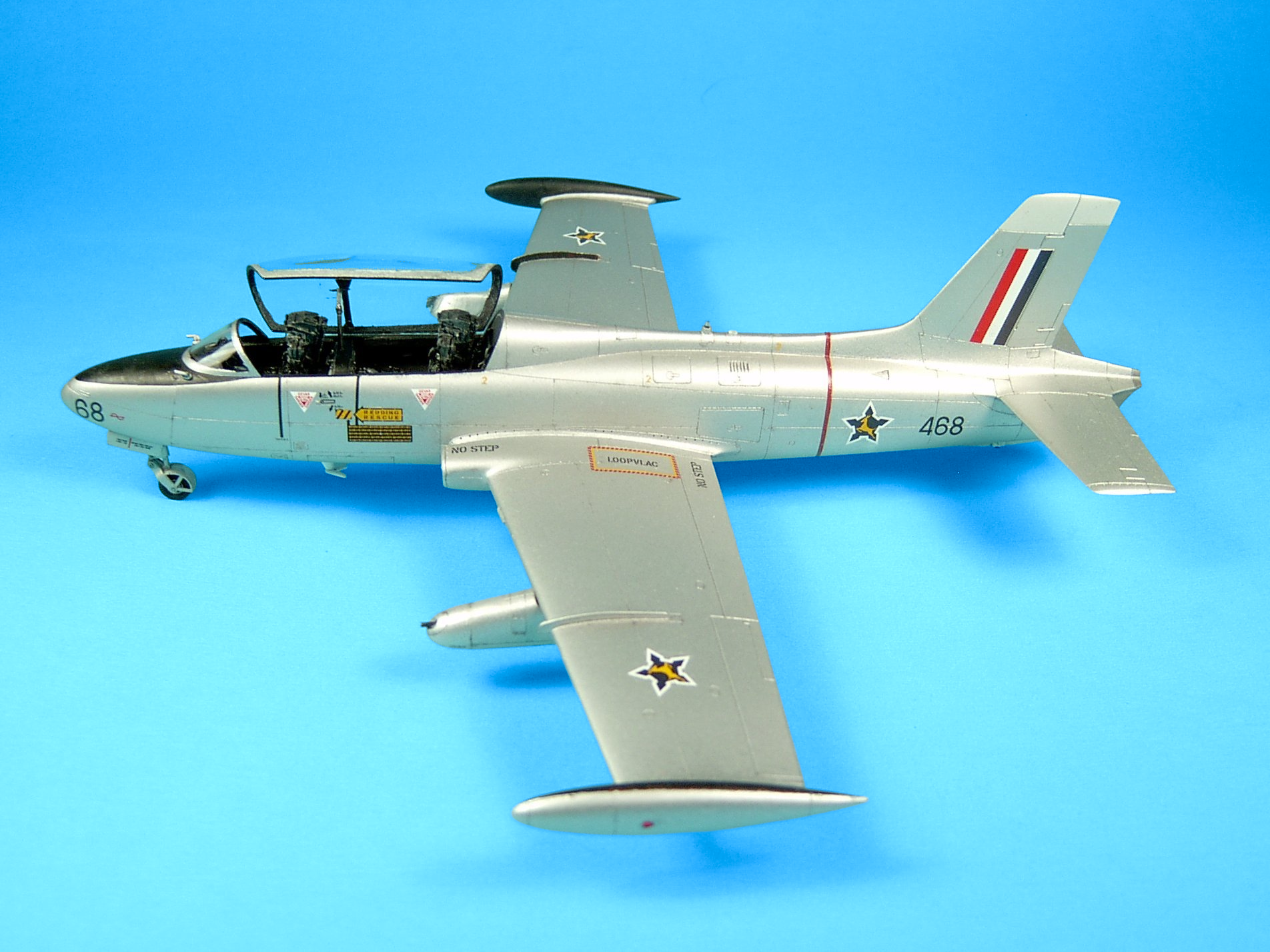
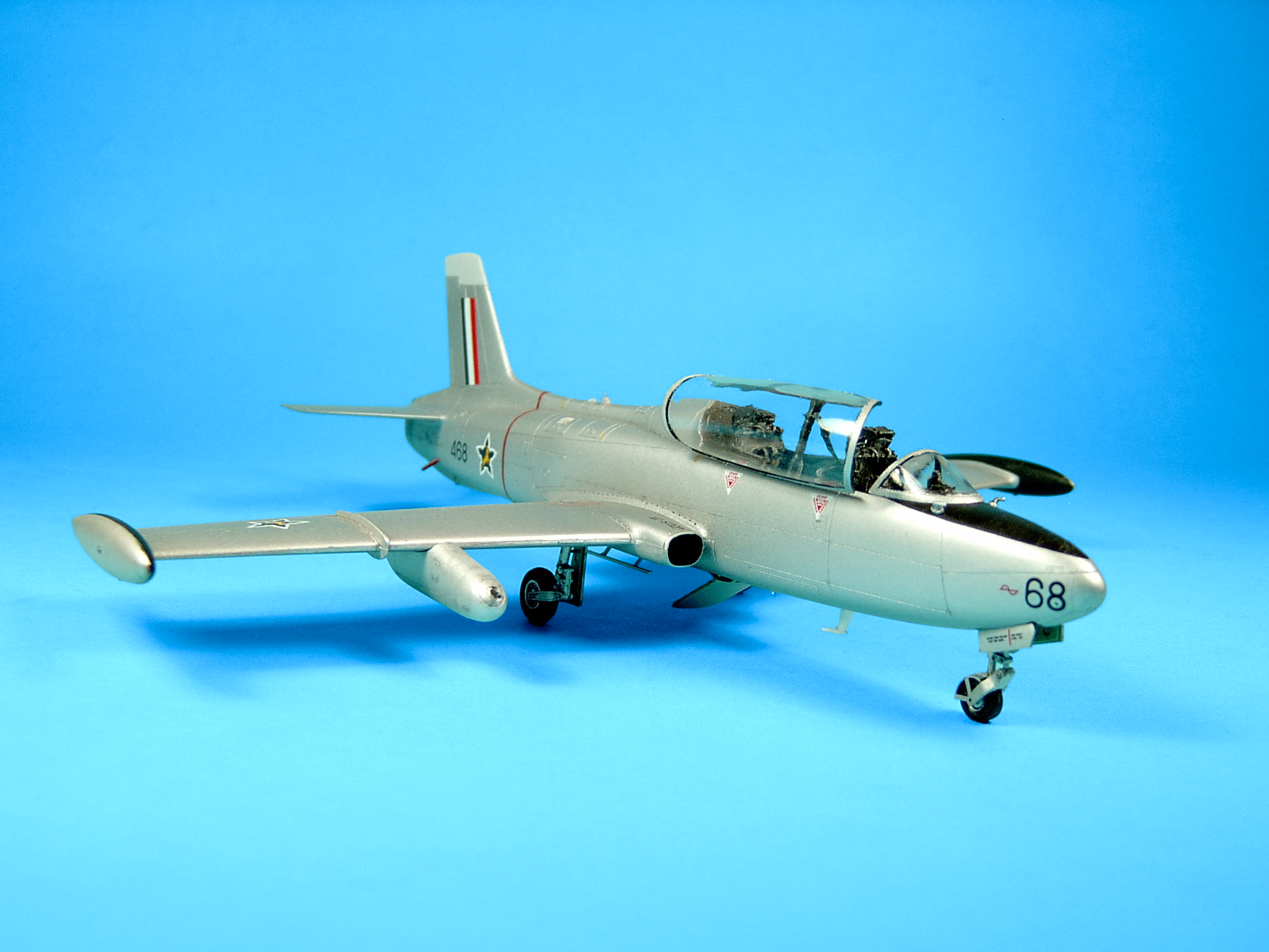
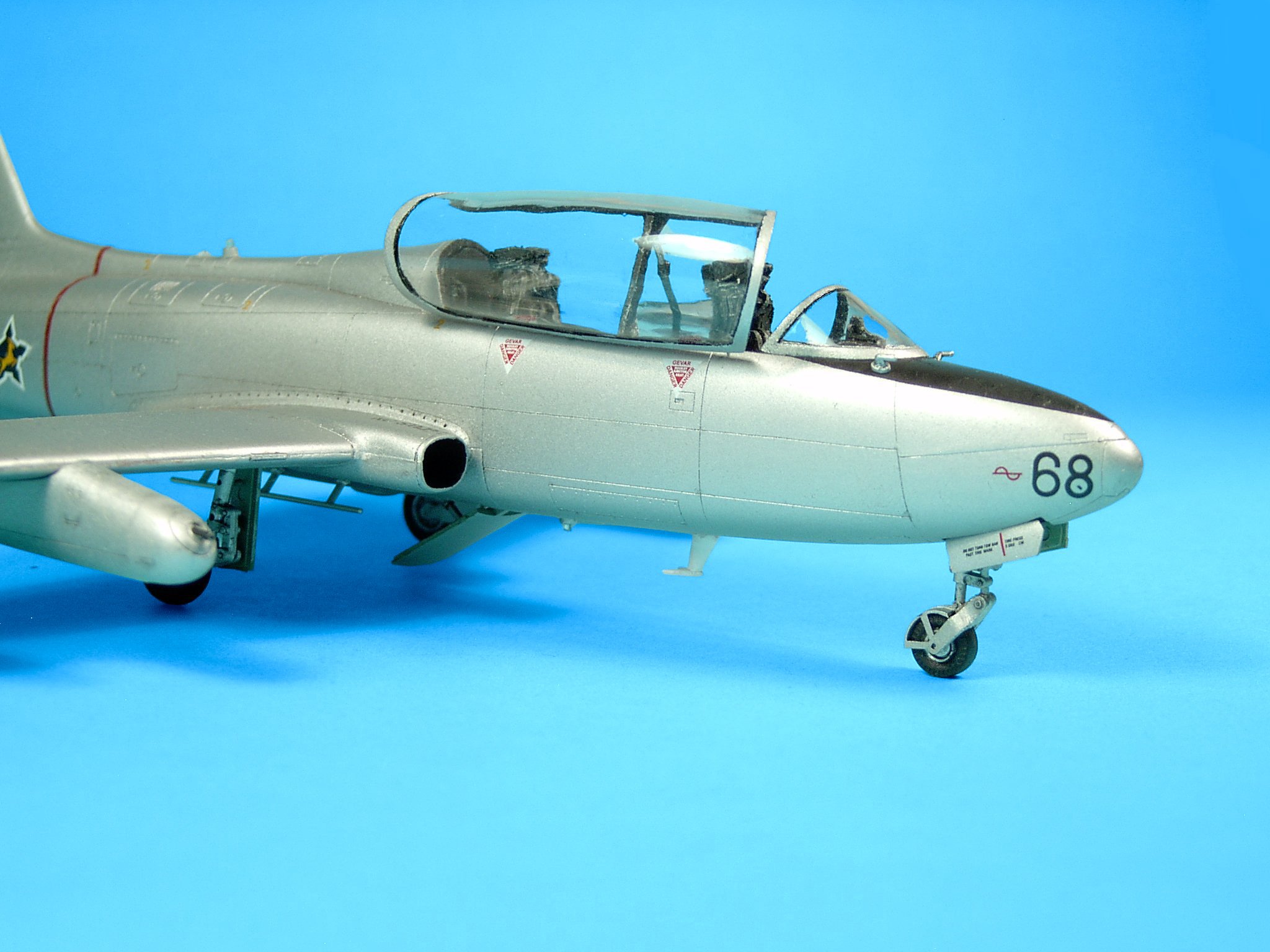
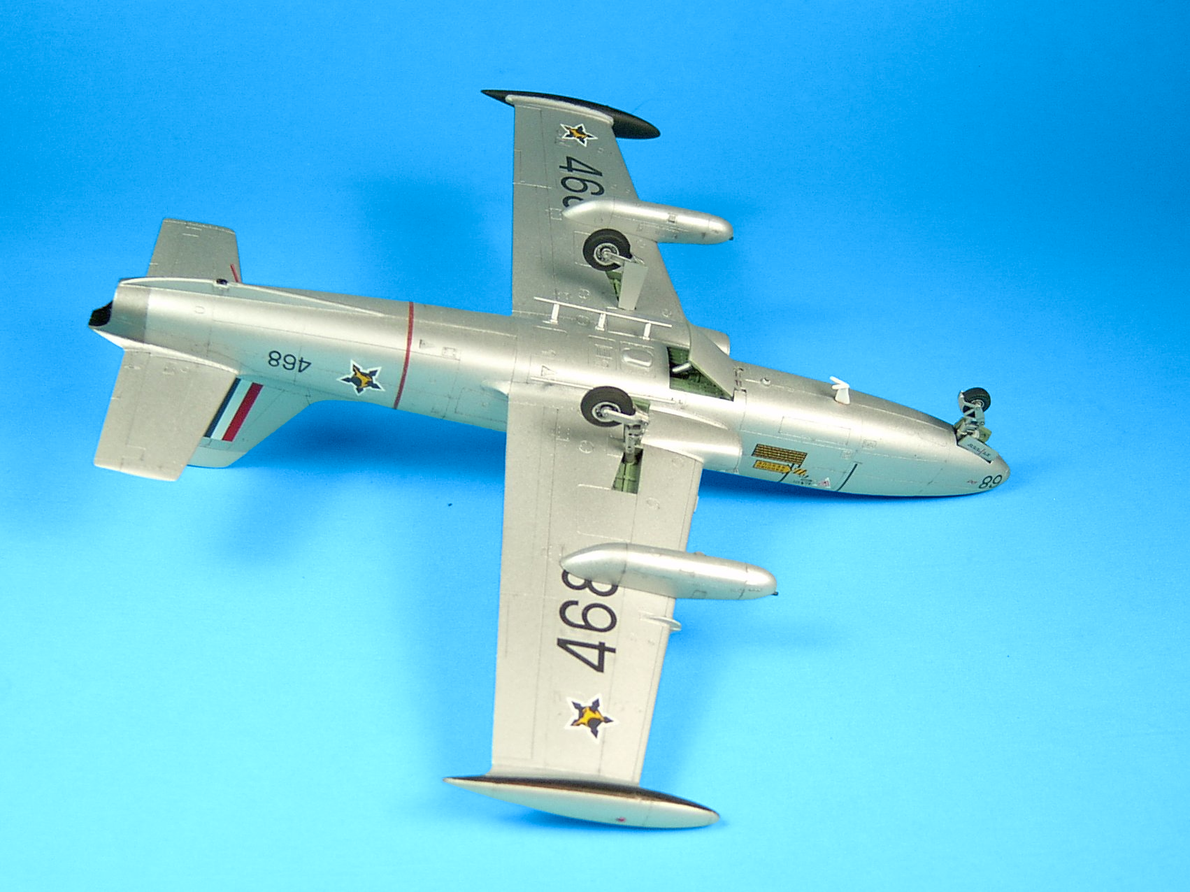
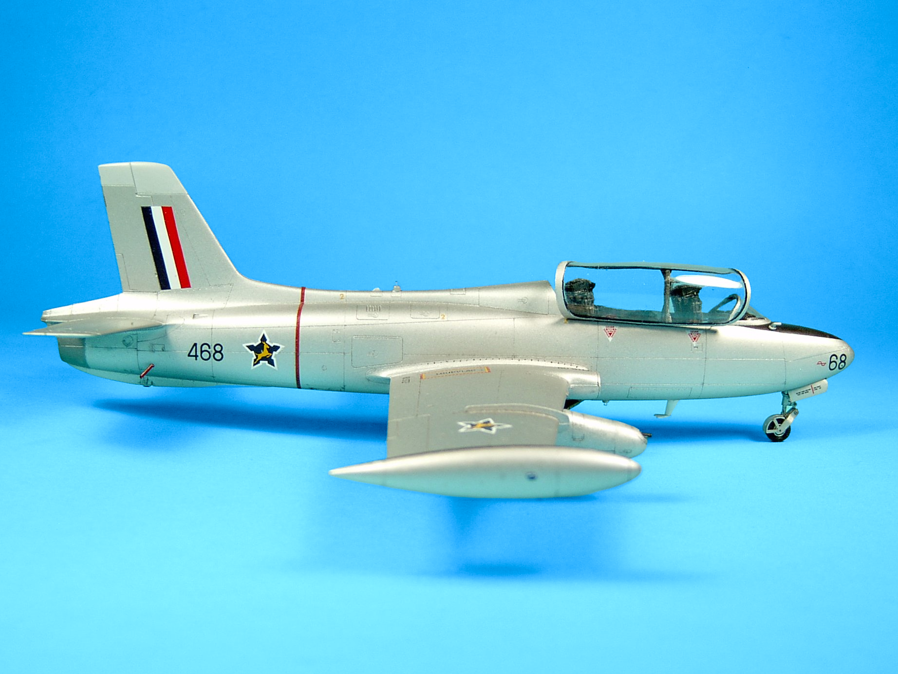
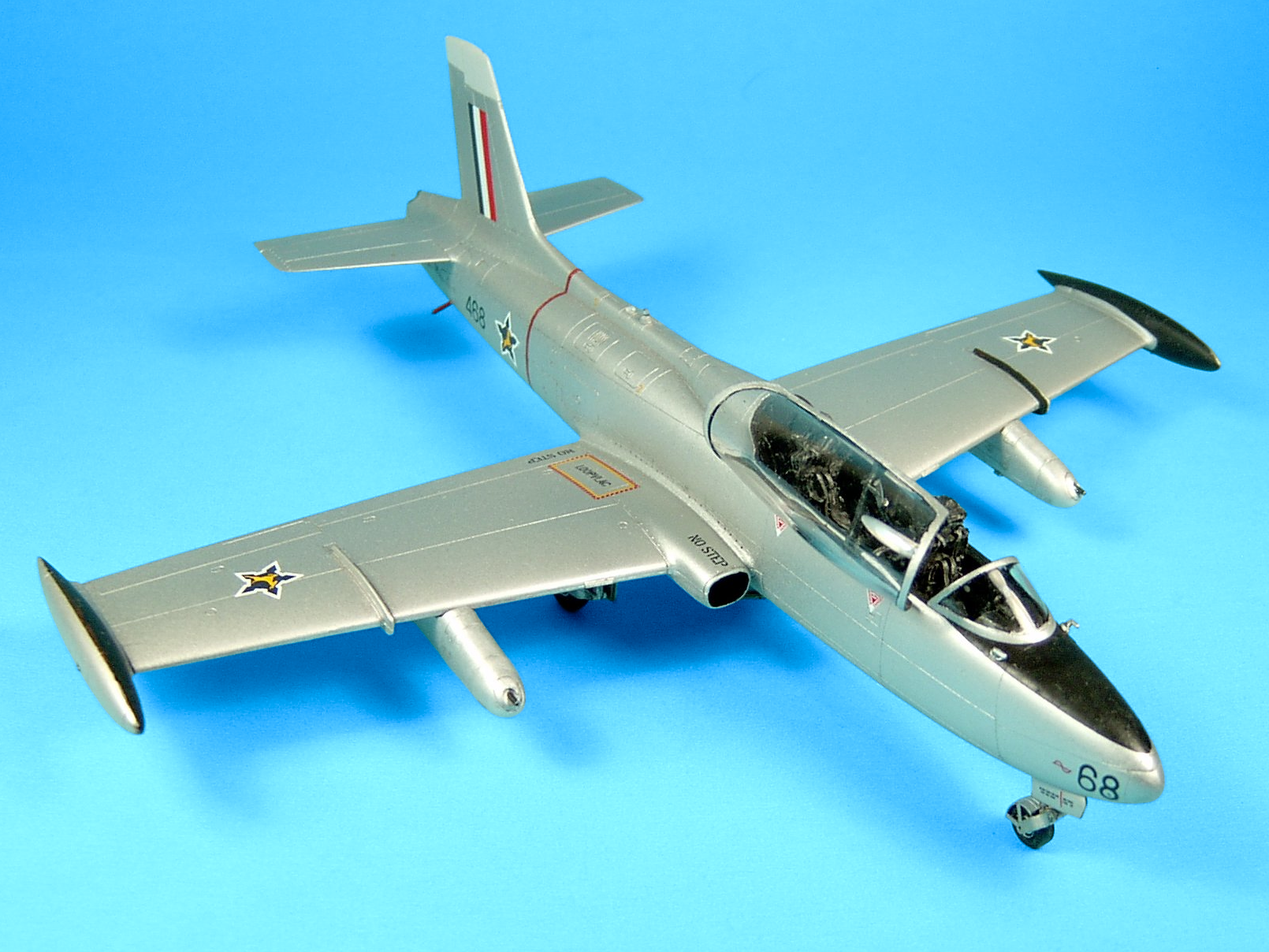
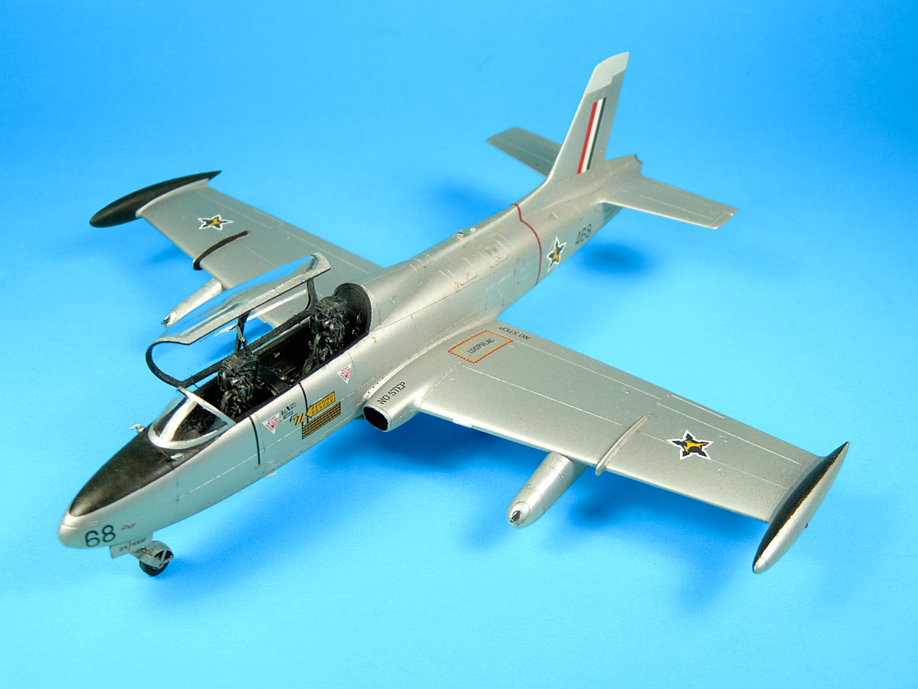
I've always wanted a MB.326 for my collection but I also wanted a MB.326 that was just a little out of the ordinary. The plane I choose to model was an Aermacchi MB.326M/Atlas Impala Mk.I of the SAAF Silver Falcons photographed in a stunning color photo with two planes banking away in formation. Since no decals were available for any of these planes I made decals for a 1/48 SAAF Silver Falcons MB.326M/Impala Mk.I 468/68 armed with two 0.5in gun pods (Stormo Custom Decals - 48001-CD).
Stormo Custom Decals - South African Macchi MB.326M/Impala Mk.I
Silver Falcons w/ 0.5in Machine Gun Pods 48001-CD
The plane in this configuration was used by the SAAF operationally and in combat during its border wars with Angola and Southwest Africa. The kit I used is the
venerable
 Italeri 1/48 Aermacchi MB-326 1/48 - IT2626
Italeri 1/48 Aermacchi MB-326 A 1/48 - IT2626
with gun pods ordered from Italeri (Part # 099997-Replacement Parts B2C-6). The kit started-out life as a 1/48 Esci kit (Aermacchi MB-326 Trainer Jet No. 4063). Italeri purchased
the moulds and reboxed the kit in 2000. The Esci kit was first released in 1981 with nicely engraved recessed panel lines, clear
parts that are well moulded and was a step ahead for the times. The first Italeri offering of this kit was released in 2004 and comes with decals printed by Cartograf for AMI,
Argentinian, Australian and SAAF machines.
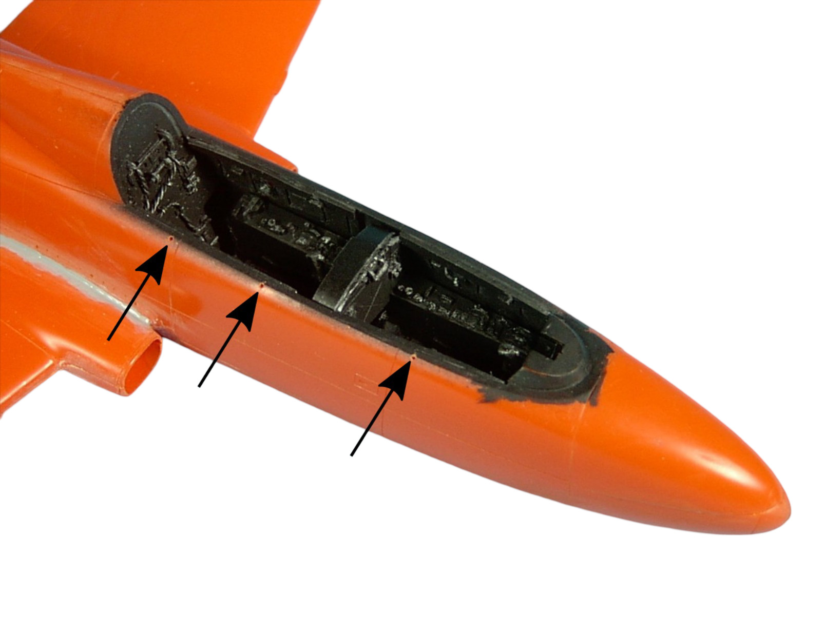
The sprues are moulded in a soft orange plastic that reacts well to liquid cement with minimal flash, and what flash is present is easily scrapped away. Panel lines are recessed. The instructions are clear and simple, there are 9 instruction panels (+1 for the gun pods) in 7 3/4" x 13" folded-format. The kit assembles easily and quickly. Measurements according to ADI #13 are accurate in the fuselage, rudder, wings and tail planes. Modified kit instructions are provided below for SAAF Silver Falcons MB-326M/Impala Mk.I 468/68 w/ 0.5in gun pods that include a modified Step 3 and Step 10 for the gun pods (click the blue button below to download the modified kit instructions). Parts are numbered from 1-99 sequentially and there are three sprues labeled alphabetically A-C although the labelling of these sprues serves no purpose other than to assist the modeller to locate a part quickly - parts are not re-numerated on each sprue. C-sprue is the clear sprue.
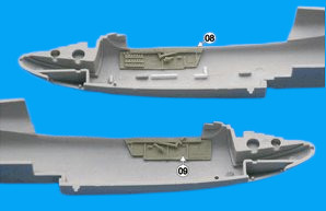
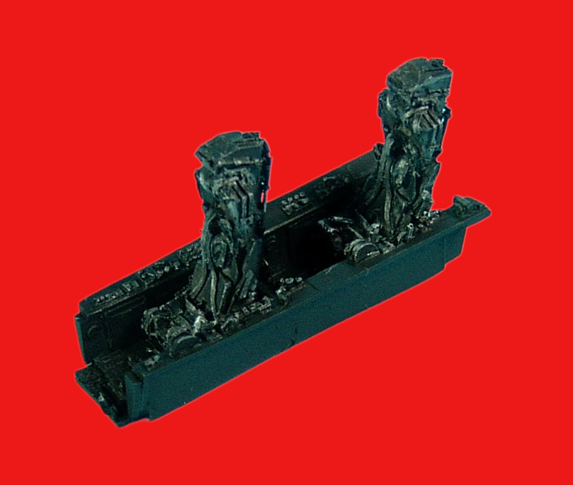
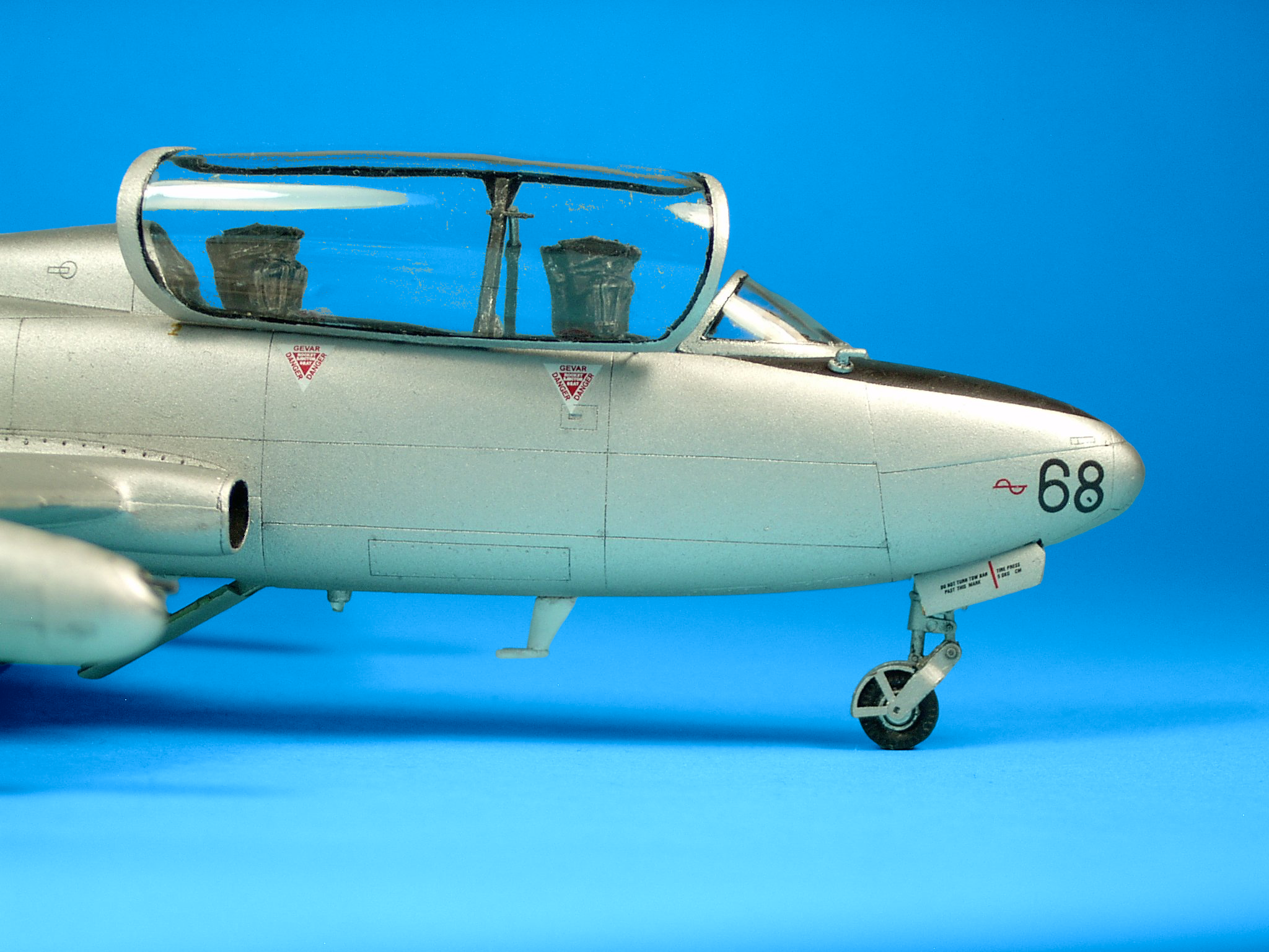
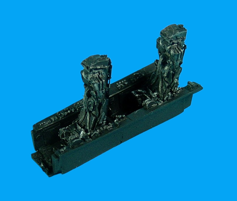
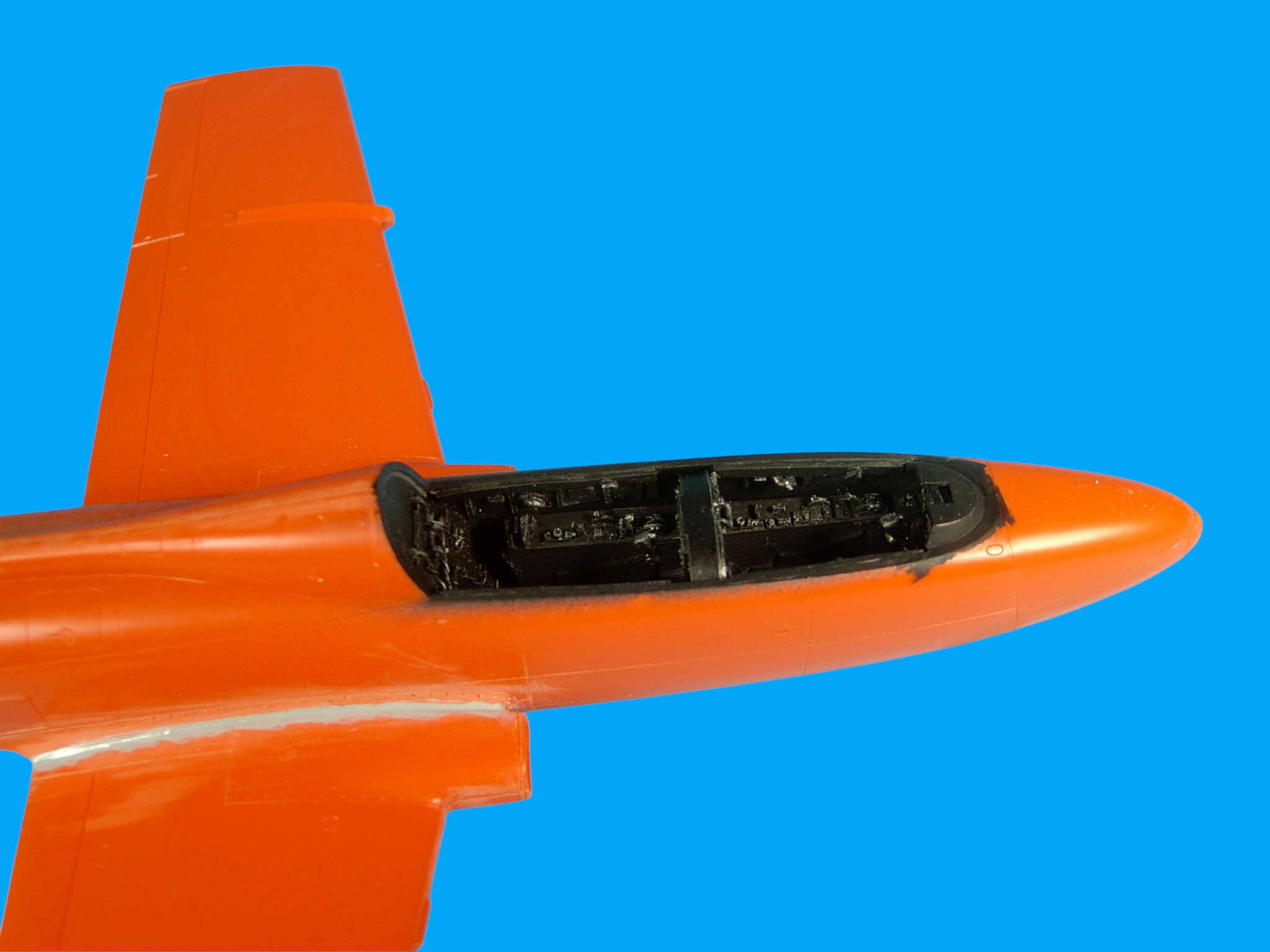
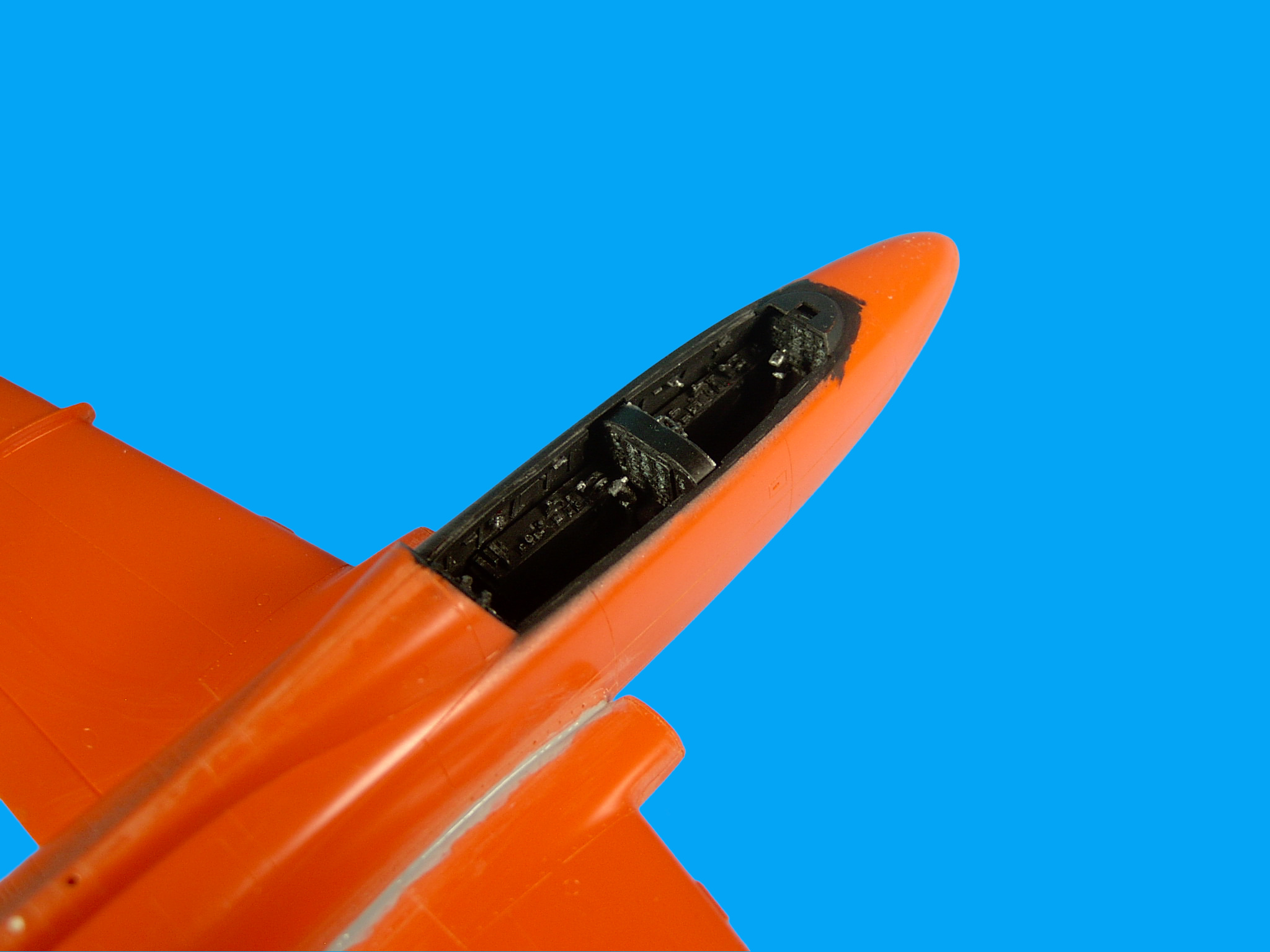
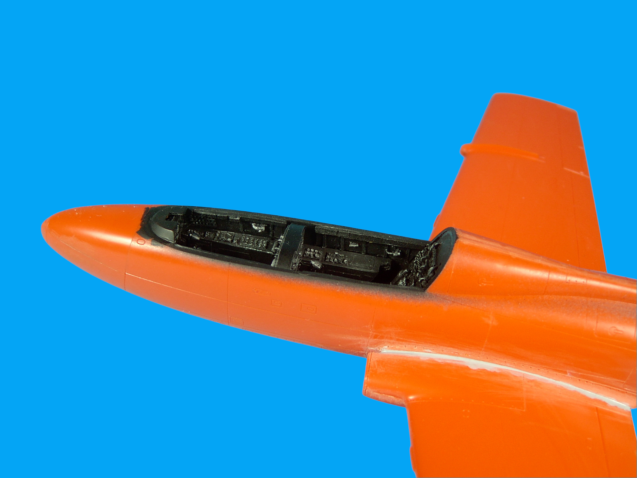
This kit is not known as a tail dragger, however I chose to add some ballast to the nose of the plane - you can do this by removing the rectangular box-like structures in the avionics-bay located on the nose to create space, this area will be covered by a hood (33A) and was meant for those who wanted to detail this part of the model with the hood in the open position. If you choose to use an after-market cockpit, be sure to clean the parts carefully using a soft brush with liquid detergent, let dry and apply a primer before painting. Cockpit: I began construction with the cockpit. Most of your time will be spent in the cockpit if you choose to add an after-market cockpit set. Resin parts are delicate, often brittle and anyone who has had experience working with this medium knows, fit can also be an issue. The kit supplied cockpit is sparse and devoid of detail, the instrument panels have no dials and the sidewalls and cockpit tub have no detail - this isn't surprising considering the age of kit although if I were Italeri I'd turn this kit into a multi-media kit adding a resin cockpit, photo etch details for the inside canopy and a open-canopy hydraulic cylinder, the semi-elliptical bars on the fin, better pitot tubes, a better fitting avionics-bay hood on the nose with detail if a modeler wants to add detail here, photo-etch cockpit details such as the instrument panel cluster e.g., Yahu, a resin gun-sight, i.e., take a page from Eduard and Special Hobby. Or better, add all of the above details in a (new parts) D-sprue. The kit supplied instrument panels do however come with well printed decals but are not convincing on a 2-dimensional, flat instrument panel. The kit suppled ejection seats are oversized for an MB-326M/Imala Mk.I, are in fact Martin-Baker Mk.4 light-weight ejection seats fitted to the MB-326GB and the prototypes. The MB-326M/Impala Mk.I was fitted with narrower Martin-Baker Mk.6 ejection seats. This is one of those kits that screams-out for an after market cockpit set, especially if you choose to model the canopy in the open position, everything inside the cockpit: sidewalls, instrument panels, seats, bulk head, control sticks are conspicuous. The short-story is, you need an after market cockpit set for this kit. I used the Neomega-resin MB.326 cockpit set C78
Neomega Resin - 1/48th Macchi 326M/Atlas Impala I - cockpit resin kit - C78
with the correct ejection seats. This set no-doubt enhances the model although the detail is a little rough
but it does the job. I started assembly of the resin cockpit by gluing the four sidewall panels to the fuselage halves as per the instructions (btw Neomega instructions are for the
MB-326K, there are no instructions for the MB-326M/Atlas Impala Mk.I although its simple enough to figure-out and in any case assembly photos are provided below):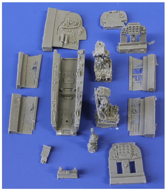


but this did not yield a tight fit so it might be better that the four sidewall panels be glued into place after the two instrument panels are attached to the cockpit tub and the rear bulk-head glued into position, to give a better fit. I chatted with Gordon Upton at Neomega and the kit resin parts are fabricated in Russia. I used Mike Grant Cockpit details 1/48 decals for the instrument dials and gauges (show image). The Neomega instrument panels come with circular recessed instruments with no detail, 0.043in and 0.033in diameter clusters. Even though I used Mike's decals for the dials and gauges I thought the bare instrument panel actually looked better with silver accents along the edges just dry-brushing, probably because the contrast with the instrument panel surface (flat black) and the instrument panel cluster itself - so no harm no foul if you choose not to add dials and gauges to your plane's (Neomgea) cockpit, and for practical considerations I don't know if Mike sells these decals anymore. The color of the cockpit interior varied in the MB.326 from flat black, gray, black and gray and a pale green. Without reference photos for SAAF MB-326 cockpits, I choose a simple flat black with sliver accents/dry brushing.


To assemble the cockpit tub to the fuselage halves, start with the rear bulk head and attach it to the starboard side fuselage half, don't attach it to the cockpit tub because the fit isn't exact and the gaps between the fuselage halves and the bulk head are too large. To do this, use two thin strips of tape to align the bulkhead, adjust and apply Elmer’s glue to fasten initially and then apply cyanoacrylate and pins made of polystyrene to reinforce the bulkhead. The bulkhead needs some trimming where the cables meet the starboard side fuselage and need slight trimming for a tight fit. Attach the forward instrument panel to the cockpit tub and fasten the tub to the starboard side and reinforce with pins and cyanoacrylate. Add the second instrument panel and control sticks. You're now done with the cockpit but this took a little longer than I expected and made up the bulk of my time on this kit. Note the top of the second instrument panel lay a rectangular metal sheet that curved over top of the instrument panel that you'll need to add to fill the gap between the two resin halves that make up the second pilot's instrument panel and the bulk head aft of the forward ejection-seat.


I can't stress enough that an aftermarket cockpit enhances this kit, it’s almost required here if you intend to model the canopy in the open position. Add the ejector seats and the hydraulic cylinder for the canopy (you'll have to scratch build the cylinder) after the kit is fully assembled. The Neomega ejection seats don't come with ejector seat firing handles and the ones that come with the kit are oversized so you'll have to make your own, use PE or you could leave them off. Also paint the inside surfaces of the forward fuselage halves black around the cockpit and nose because the orange polystyrene is visible when the cockpit is open when looking at the forward instrument panel from the rear of the aircraft. Paint the top of the forward instrument panel deck black and mask this area for exterior surface painting. The NeOmega resin control sticks are copies of the kit supplied ones but are not well moulded, so use the kit supplied ones instead, remove the bottom pins on each stick so that the control sticks lay flush against the cockpit floor. Paint the inside exhaust tube halves and rear engine blades black with silver highlights.
Fuselage: Now assemble the two fuselage halves and you're done here. Do note that the recessed panel lines are somewhat shallow, especially on the lower fuselage indicating wear of the moulds over the years after so many stampings, so it's a little tricky restoring panels lines along the seams. I added about 3g of ballast to the nose (in the avionics compartment by removing the rectangular (box-like) structures meant for detailing) however because of the way the plane sits you may not need ballast and the instructions don't say that you do, although my plane felt nose-heavy with the ballast I added. Drill a hole for a dorsal beacon and remove and patch the second light aft of the beacon to be replaced with a clear bulb.
Wings: Because we're adding 0.5in gun pods, note that there are three narrow rectangular perforations on the insides of each lower wing (1A), you need to cut-out the openings nearest the fuselge (see Step 3 on Page 3 of the Modified Italeri Instructions for STRM 48001-CD - click the Download button above) - use an exacto knife to open the perforations. Other than that the wings are straight forward and assemble easily with no fit issues. Wing Roots: Next attach the wings to the fuselage. There are gaps between the wing roots and fuselage at the leading edges of both wings, and about a 1/32in high relief along the whole wing-fuselage. You'll need to apply several layers of Mr.Surfacer 1000 from a bottle to fill in these gaps together with sanding (Mr.Surfacer dry’s rapidly in about 30mins), alternate between sanding and filling until the gap is removed and the wing is flush with the fuselage. It seems others that built this kit did not have gap issues and the wings and fuselage in some cases even snap into place but the gaps on mine were significant enough to be annoying. Be patient and be careful with putty because of the detail in this area. There has ever only been one tooling of this kit so I'm not sure what could have created such a gap to deal with. Anyway to eliminate the gap I started with an application of Mr.Surfacer 1000 (figuring it wouldn't be a problem to deal with this gap since I've never encountered a gap I couldn't handle in all the years) from a bottle using a Model Master/Testors 8832 Type 0 brush to fill the gap after gluing. A few applications of Mr.Surfacer were needed but it still wasn't enough. I then applied Vallejo Plastic Putty 20ml Tube 70401. I don't like to use putty in any situation because it creates more problems than it solves and also, there are other ways to elimate wing-root seams, albeit tedious but more effectively without materials such as gap fillers and putty that generally obliterate detail, and that's the problem I ran into here, there's enough detail, rivets and seam lines around the wing roots that I didn't want to lose. Anyway because of the width and depth-relief of the gap I was forced to use putty now that the wings were glued into place and the gaps had to be eliminated because of the aluminum finish. I examined other builds of this kit for traces of the same problem but I didn't notice anything and in one video the wing root and fuselage slid into place, flush, with no gap or relief and no corrections were needed, but not so on mine - so I was left wondering if this was some kind of bad batch. Anyway, I applied putty and more Mr.Surfacer followed by sanding and a final application of Mr.Surfacer. The soft plastic helped eliminate the gap somewhat during sanding while trying to preserve the detail in this area. I've never encountered a gap issue like this one (that annoyed me so much because it’s an aluminum aircraft, and 2-dimensional in error y-z), all the more surprising since everything else went together nicely. When done with Mr.Surfacer clean your brush with Lacquer thinner. Underside engine nacelles: Clean each nacelle and be sure to align the parts against each wing applying a light force toward the aft of the aircraft so that the nacelles snap into place and are flush and with the panel lines, then glue. Some have reported fit issues here, however I observed none on the port side but the starboard side needs to be sanded and fitted. Canopy: The clear parts are well moulded. I drilled three pilots for the canopy hinges using a #80 drill bit. I tried using painters tape around the canopy to protect the canopy from fingerprints but the tape interestingly left behind a residue, although the residue was easily wiped-away with a fibre cloth (don't use sticky painters tape in modeling). After the canopy was wiped clean I dipped the canopy and windshield in Future and let dry. I masked the canopy and then fit a slightly curved rectangular bracket that was used to lift or operate the canopy open via hydraulic cylinder. This took a little longer than I expected but it’s worth the added detail. I applied thin strips of tape onto the canopy to align the location of the canopy hinges to the holes that were to be drilled into the fuselage, with sticky side facing the fuselage, I aligned the canopy to the cockpit and then removed the thin strips of tape from the canopy so that the tape indicated where to drill the fuselage. This is a delicate process and you need to be careful not to damage the fuselage or resin cockpit walls. Insert thin wire into the canopy hinge-holes and use a tiny amount of Elmers glue to fasten and test fit the hinges. Remove the hinges and glue and reinsert the hinges after painting and modifications to the canopy are complete.
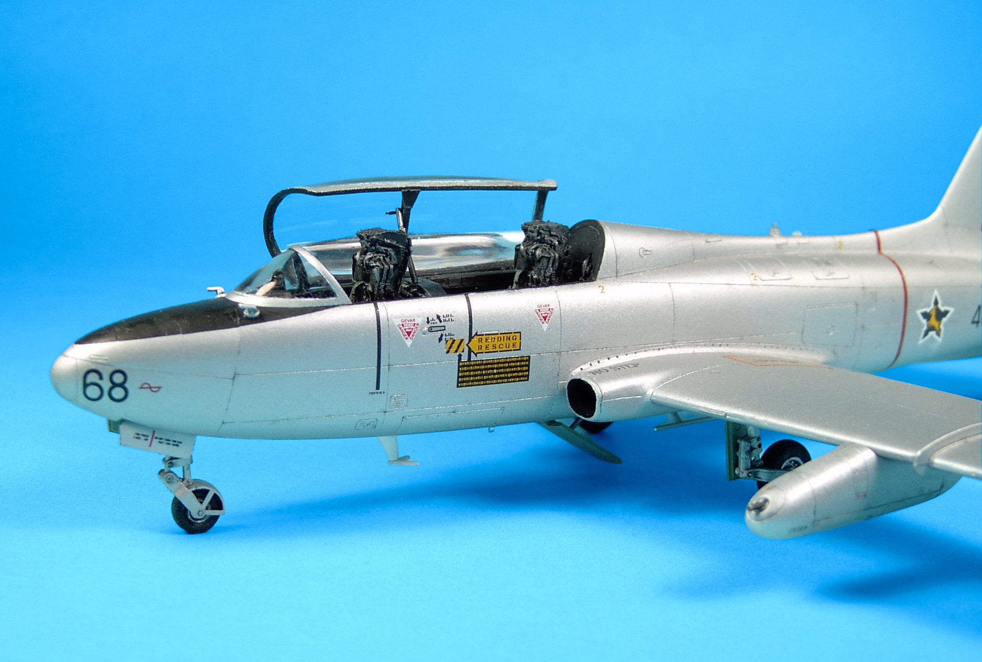
Windshield: I masked off the windshield and applied a layer of flat black to the inside and outside of the canopy and then applied Humbrol 27001 Metal cote to the exterior frame. The Metalcote tin was at its end and sprayed poorly with heavy grains, perhaps more solvent might have helped. After drying I sprayed on an acrylic flat to help eliminate the graininess of the Metalcote. I've used Humrbol enamels in the past and these paints are an old formula. For a realistic metal finish use lacquer metalizers my favorite being Modelmaster Metalzier Lacquers (if you can find them), these paints spray the same when you first open a bottle to the last drop - there's no waste. Humbrol use oddly-shaped tins that are difficult to work with, there's allot of waste, they don't seal properly and the residue is virtually unuseable, they also make a mess and the residue clogs your airbrush. On the positive side, Humbrol enamels are durable and can be worked with easily during weathering and masking, and adhere to plastic well so you don't need a primer. Not surprisingly I had 27001 bleed underneath the masking tape (first time to this extent!). Because the canopy was dipped in Future it was just a matter of using a 0/10 brush and dipping it into solvent/thinner and gently removing the paint. There was also bleeding along the edges of the rear frame so I dry brushed the this area black. Gun pods: Refer to the modified instructions page 7 Step 10. Note that the orientation of the gun pod apertures for the gun barrels are oriented off-center of the pods, refer to the photo below. The gun pods can be assembled at any time but should installed at the very end.
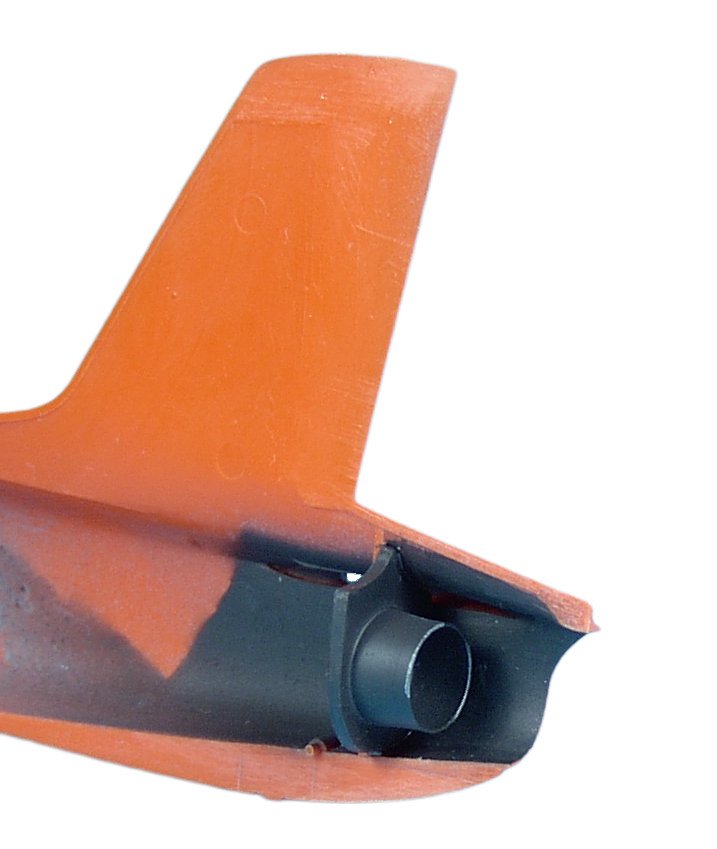
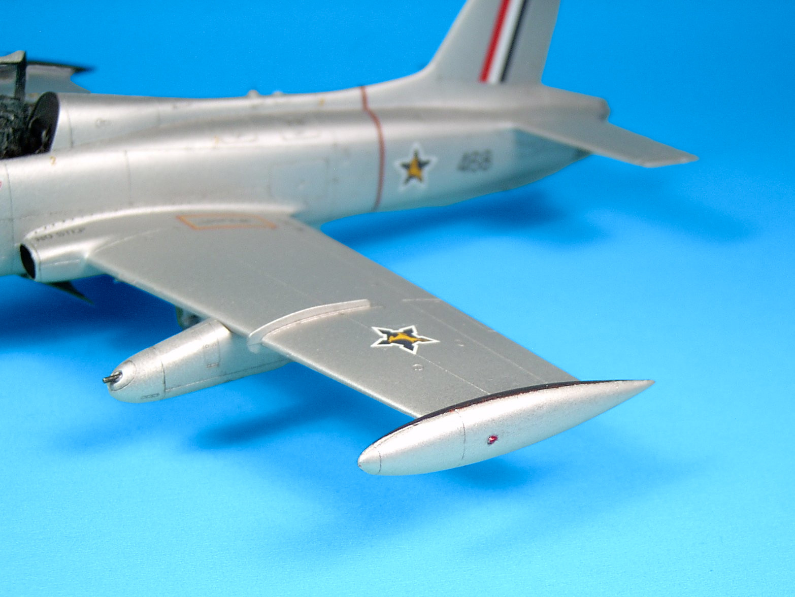
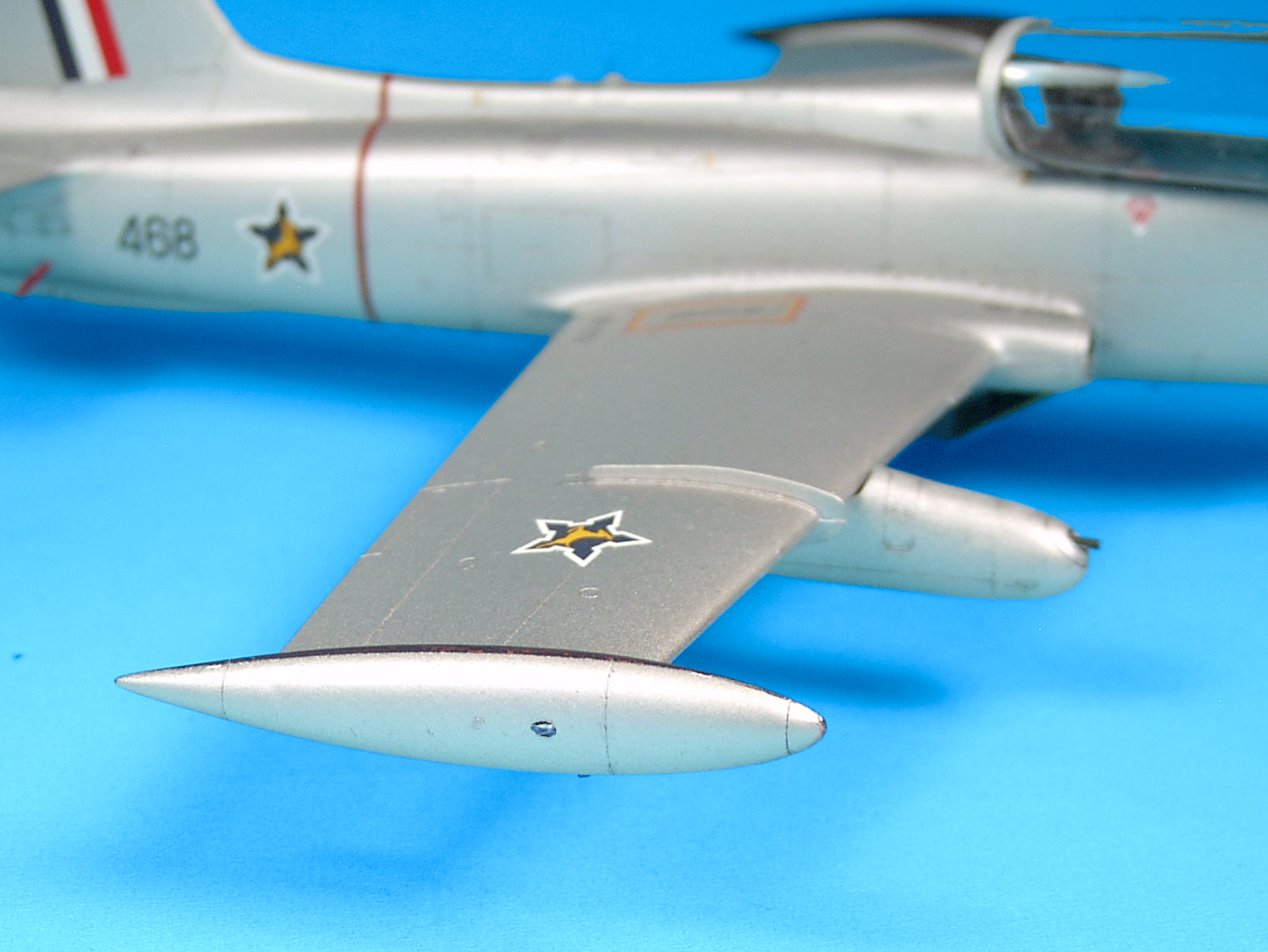
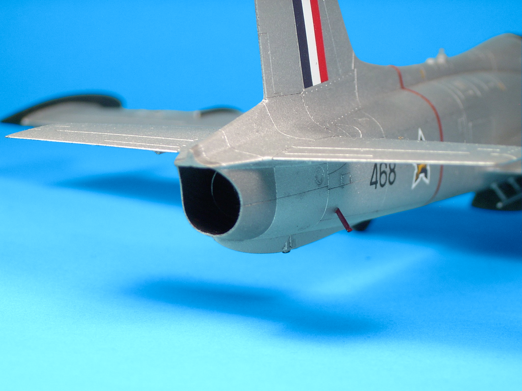
Wing Tip Fuel Tanks: The wing tip fuel tank halves fit tightly together and have pretty good detail. Be sure to fasten the tanks to the wings with the protruding notch (empty pipe) facing downward and the circular refuel hatches facing upward. The port-side fuel tank fits tightly and smoothly to the port-side wing. The starboard side fuel tank fits tightly but at a slight angle so you'll need correct this with some sanding. The wing tip fuel tanks were removable and the plane could be flown without them. Rudder and Vert. Stabilizer: South African MB.326s lacked the semi-elliptical handle on the top of the fin as well as the hook on the tip of the nose. The instructions show the horizontal stabilizers and elevators (cast as a single part) facing the wrong way up (with the rectangular panel closest to the fuselage facing upward) however the guide pins prevent gluing these parts the wrong way - a design feature that kit manufactures should follow in general. The fit is tight with no gaps and the dihedral is good. Some have reported gap issues here but I got none, contrast this with the gaps I got in the wing-roots while others reported none.


Beacons: Aircraft beacon lights are red in color and either flash or rotate to provide a pulsating warning light and are typically installed in pairs with one on the top of the fuselage and the other on the bottom. Beacon lights on SAAF MB-326M/K were shaped differently than other variants, incorporating a stepped design, suggesting local manufacture of these devices, but oddly, although the beacons on MB-326s delivered to every country except South Africa were housed in an equal-dimeter cylinder with a red bulb atop the fixture, SAAF beacons used white bulbs instead, housed in a cylindrical design with the bulb in a narrow-diameter housing atop a wider base-cylinder. Aircraft delivered to Argentina, Australia, Brazil, Italy etc all used red beacons. I haven't been able to determine why this was so but unfortunately the kit doesn't come with a SAAF dorsal beacon despite markings for SAAF MB-326Ms, so you'll need to add your own and you can do this by drilling a hole in the upper fuselage, make a base cylinder (2.2mm D x 1.0mm H) from stretched sprue, drill a second hole over the base cylinder, stretch clear sprue and insert over top the base cylinder for the white beacon (1.5mm D x 0.665mm H). There's a second smaller bulb behind the white beacon, I removed the one that comes fixed to the kit in parts A15+A16 and added my own tear-drop bulb from clear sprue 1.9mm D + 0.8mm H. Use a flat filer to level the top of the base cylinder. The process above was repeated for the ventral beacon.
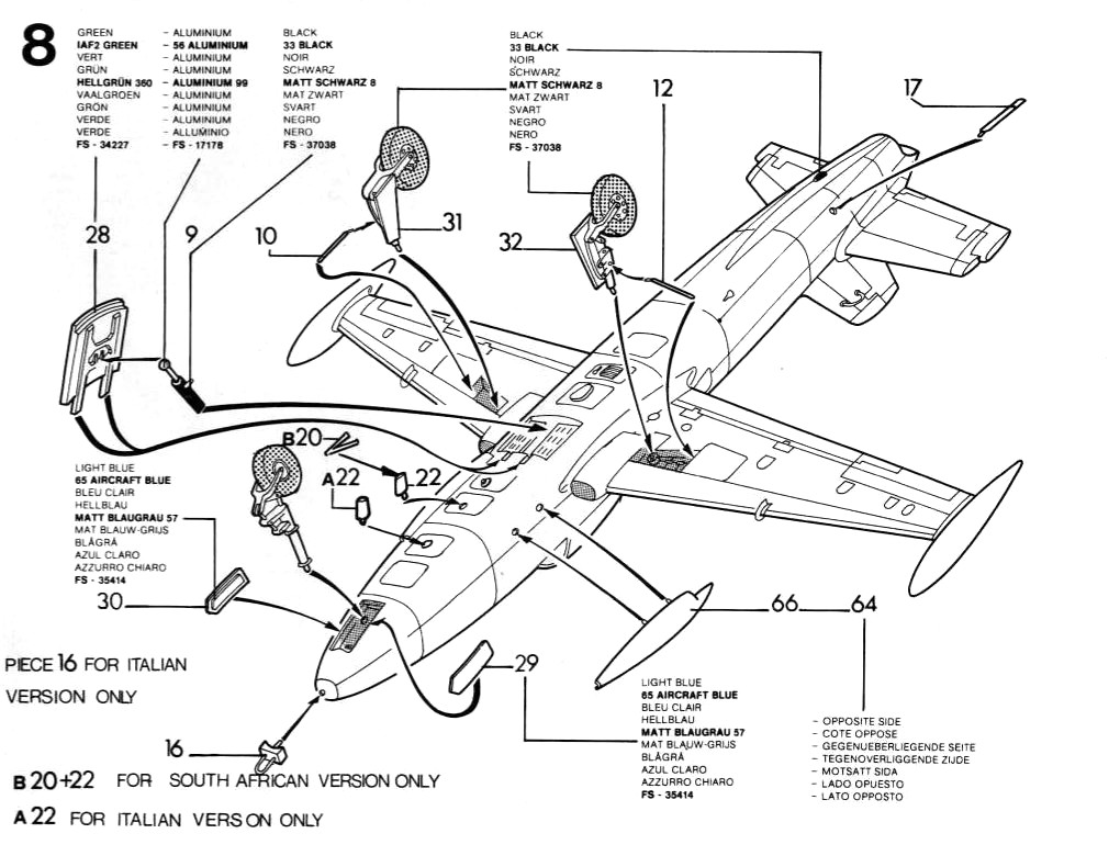
Ventral Antenna/Fin: Although the kit comes with SAAF markings and SAAF MB.326s were equippped with radio equipment and an antenna on the lower surface below the cockpit, and the kit comes with the necessary parts to add this apparatus (A20 + A22-Italeri kit parts), the Italeri instructions are missing this step - the original Esci instructions however do include the step to add the ventral antenna/fin. Below is Step 8 from the Esci instructions Impala Mk.II/MB-326K Kit.4060 - note that the location of the antenna was the same as on the MB-326M/Impala Mk.I. Assemble (B20+B22-Esci Kit parts - A20+A21 Italeri parts), drill a hole in the lower fuselage and mount. Although the Italeri instructions are simpler than the Esci ones, and it really is no big deal to add the antenna, the modeller shouldn't be expected to hunt around for Esci instructions, or worse missing this step entirely - this step needs to be added to the Italeri instructions.
Exterior Paint: MB.326 exterior aluminum appears as a dull flat like finish (dull-Aluminum or Aluminum plate) - see the photos above, so I thought Humbrol Metalcotes might be a good option for this plane. I had only a small amount of Metalcote 27001 remaining and I applied it to the windshield and canopy, and as with my Hobbycraft 1/72 Canadair CL-13,
Hobbycraft 1/72 Canadair CL-13 Mk.IV/F-86E(M) by Vince Tassone
Metalcotes finish with a slight graininess, so for a better finish use Testors Metaliziers (if you can
find these paints) or Alclad II. I started painting with the wing-tip tanks and inside fences as well as pre-shading the wheel wells with Modelmaster flat black acrylic which is the old Polly
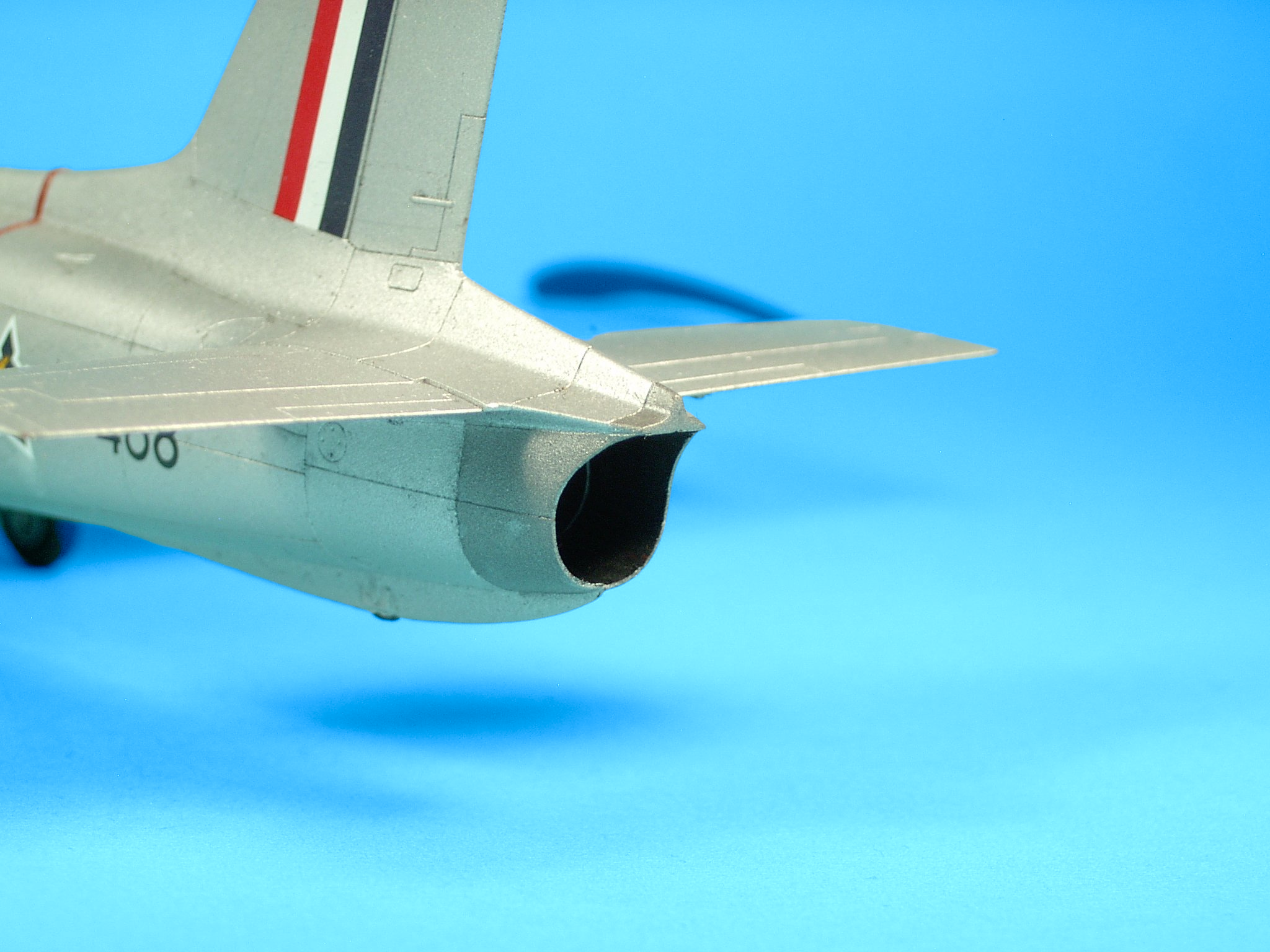
Scale paints and sprays on well. I also painted the insides of the engine air-intake and exhaust black.
I then painted the exhaust-pipe exterior with Gunze Steel but it sprayed-on with a high-graininess and high-gloss (it looked bad and unrealistic), so I sprayed over it with black and then tried
Modelmaster Metalizer Steel and the shade was too close to aluminum so I finally tried
 Alclad II Dark-Aluminum
Alclad II - Dark Aluminum Finish 1 Fl. Oz. - ALC103
and this looked fine. I then sprayed on a sealer for masking. After masking the tail-pipe exterior
I sprayed Modelmaster Acryl 34227 Pale Green into the three wheel wells and air-brake compartment and masked each of these areas. I painted the top of the fin and rudder Gunze
H338 Light Gray 36495. It was now time to spray on aluminum, and for this I had a tinlet of WEM Aluminum enamel paint I wanted to try. The paint in my tinlet was viscous but I was able to thin it
with ModelMaster enamel thinner 50/50. This paint atomizes like-crazy, anything nearby will get coated with tiny spots of aluminum. I applied this paint, a single layer to small parts and
to the top of the model first. The finish is not as good as Humbrol Metalcotes and the graininess is apparent although it sprays on a little thinner than a regular enamel but it’s still an enamel
and I have yet to see enamel paint that can finish like a lacquer. WEM Aluminum dries pretty quickly within 2-3hrs and you can try buffing it lightly to eliminate paint speckles. WEM Aluminum is fine
for smaller parts but I don't recommend this paint for larger areas such as the wings and fuselage. I let the top dry overnight and painted the bottom of the plane the following day. The graininess
and tiny speckles of pink and purple under intense lighting used in photography made this paint unsuitable as a final finish. In the past I've used enamels as a base coat or primer for Modelmaster Metalizers
and I did the same thing here. In terms of shade, WEM Aluminum is closest to
 Alclad II White Aluminum.
Alclad II - White Aluminum 1 Fl. Oz. - ALC106
The bottle of Alclad II White Aluminium I had was surprisingly viscous, especially compared to
ModelMaster Metalizers. I didn't thin my Alclad II White Aluminum but increased the airbrush pressure. Others have reported this issue with Alclad II paints and in some cases even thinned the paint
- something I never had to do with ModelMaster Metalizers. I also found that you have to get fairly close to the model when usign Alclad II to get better coverage, possibly because of the viscosity of the
paint but again something I never encountered with ModelMaster Metalizers. Alclad II sprays on well but the coverage is not that great, requiring a closer distance when spraying as I mentioned above,
something I wasn’t used-to. Alclad II White Aluminum does spray on well, its better than an enamel, and acrylic metal paints I've tried (although I haven't yet tried Vallejo Metal Color). No
graininess and the finish is dull and bright as were the Macchis. A benefit of lacquer paints is that they dry fast as opposed to waiting a minimum of 3-6 hrs for enamels to dry. To my surprise
Alcald II White Aluminum is fairly-durable. I should point out that Alclad II appears to be sensitive to the base coat or primer, in this case WEM Aluminum - and what I mean by this is the finish
is affected - see the various primers recommended by Alclad II e.g., black gloss and gray primers which evidently supports this observation. I'll look into this more the next time I use Alclad II paints
but once again this was not the case with ModelMaster Metalizers that sprayed-on beautifully over enamel undercoats or primers, or almost anything else including a flat black acrylic primer. Use
Alclad II undercoats/primers - follow their system. I lightly buffed the whole model and applied ModelMaster Metalizer sealer. I then began unmasking the wing-tip tanks and fences and I noticed
quite a bit of lift. I don't recall ever having this issue with Polly Scale paints that stuck to any surface well, even resin. It seems as if Rustoleum changed the formula of these paints although
the plastic surface might have used additionally cleaning and the paint additional curing. One of
the advantages of using Polly Scale paints was that a primer wasn’t needed, and this was important for a model like this one, in particular because of the age of the mould and the thinning of the recessed
panel lines after so many stampings. Anyway, use either a primer or at least two coats of Modelmaster Acryl if you plan to mask and/or handle the model with these paints which are difficult to
find anyway - like all Modelmaster products.
Decals: I used Stormo Custom Decals 48001-CD MB-326M/Impala Mk.I
Stormo Custom Decals - South African Macchi MB.326M/Impala Mk.I
Silver Falcons w/ 0.5in Machine Gun Pods 48001-CD
together with the kit supplied decals printed by Cartograf. I sprayed on a light mist of Polly S Gloss. Stormo Decals went on well, be sure to trim each decal as close as possible to the decals
to cut down on carrier film, you need just one or two coats of solvent to set each decal. The red fuselage band is 0.819mm wide, and the circumference of the fuselage at the band is 82.87mm in 1/48,
the kit comes with two 1mm wide and 100mm long decals which are too wide, too long and the red is too light. You can use the kit supplied decals as is, or trim the width using scissors (don't use an
Exacto knife), as well as the length or use the red-bands (decal 9) that come with Stormo Decals which are exactly the width you need and the correct color and length. Water bubbles got trapped
underneath the SA tri-color on the fin,
use a pin to prick the bubbles and gently tap the decal with a cotton swap to flatten raised areas and to absorb the water. The anti-glare panel is a challenge to get right if you choose to paint it on,
or use decal 8 in 48001-CD. If you use a decal be sure to use setting solution and use a pin to prick water bubbles that form, also use a cotton swap to gently level raised areas. I used decal 8 from 48001-CD
for the anti-glare panel. A decal will conform to any surface provided you pay attention and take your time to set it properly. I also noticed some of the kit supplied decals were disintegrating, possibly
due to the matte finish but if this happens apply Microscale Liquid Decal Film using a flat-brush to the remaining decals and note that you'll need to keep your decals in water longer when you use this solution.
If you get excess film residue after applying the decal, apply solvent to that area and use a pointed brush to gently remove it. One light coat of film is enough, if you put on a heavy coat(s)
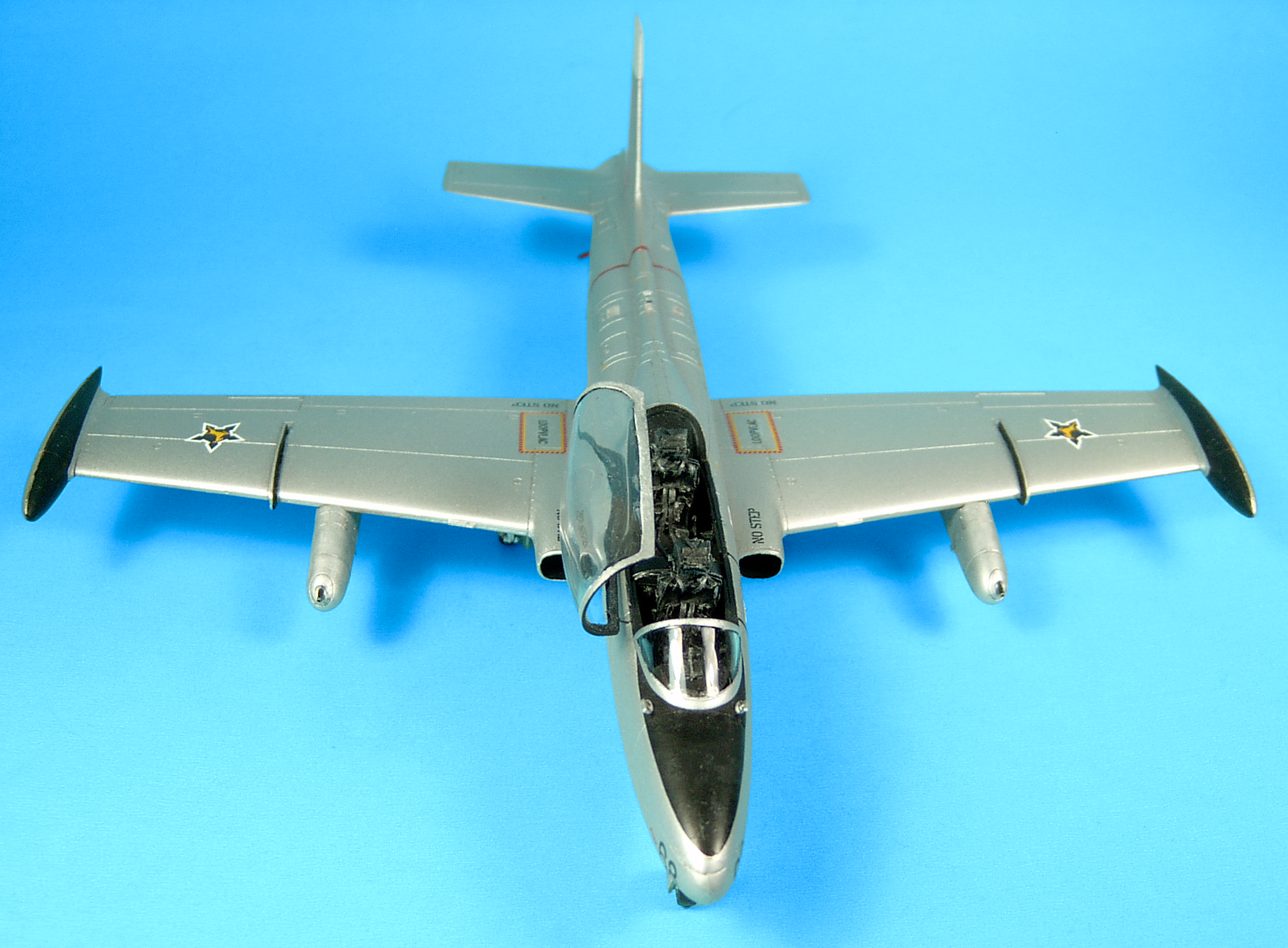
the decal will be difficult to remove from its backing. Note the stenciling on SAAF MB-326s were in English and Afrikaans, for example the inner-wing walk-ways were stenciled "Loopvlac" and the
inverted warning-triangles below the cockpits are labeled "Gevaar" (Danger), referring to the ejection seats. Decaling is a delicate, time consuming process, you need to concentrate and take your
time to do a good job. Be attentive and be patient. If you rush this step you'll get less than optimal results - decaling is an art as much as assembly and painting, it's an important part of
finishing your model properly. Treat each decal separately,
no matter how small, don't decal all at one time. You should apply enough solvent to each decal so that the carrier film dissolves and you're left with the decal pigment for a painted-on look. This
may require applying a few light layers of solvent until this look is achieved. I should also mention that this build is the first time I tried not applying solvent or a setting solution as an
under-layer before applying the decal - I just removed excess water from the decal and then applied solvent over top the decal and the results were the same as using a setting solution underneath,
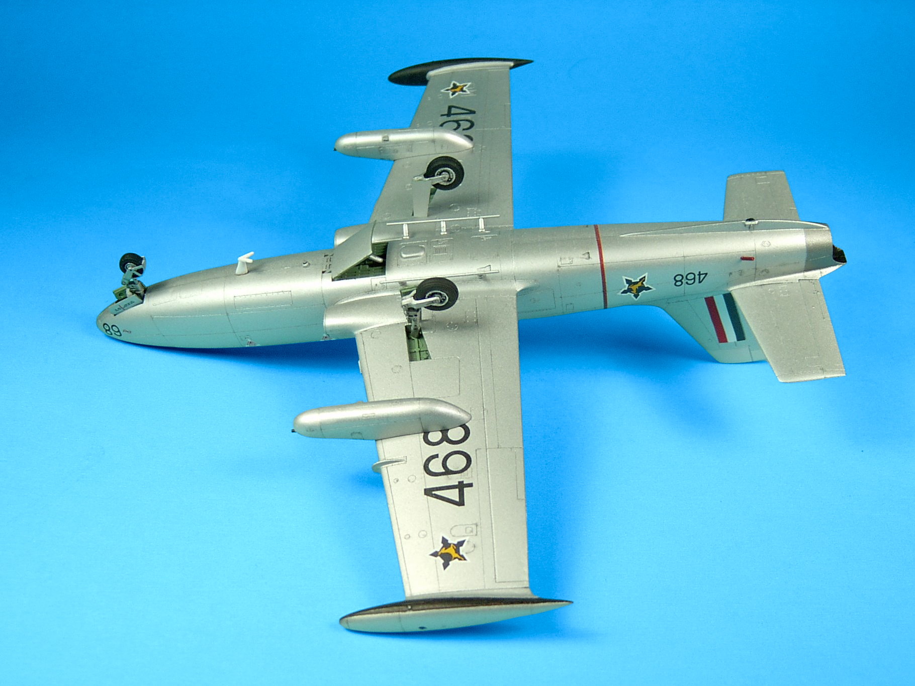
although this may have had more to do with the quality of the decals.I didn't use the kit supplied decal 3 because it’s oversized and there's no room for it if you place decal(s) 2 in the correct positions, in fact the kit supplied decals 1, 9, 10 and 19 are all oversized. The kit supplied decals 7, 8 are the SAAF "roundel"
SAAF "roundel" 1958-1981
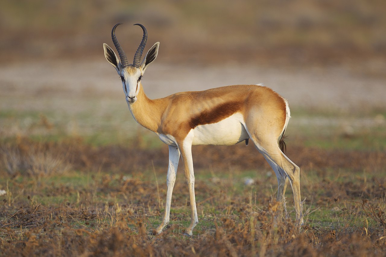
(and somewhat undersized), or the wing and fuselage markings used from 1958-1981 with a yellow
(South Africa's national animal) centered within a blue outline of the top-view of a star-fortification, oriented facing forward on the fuselage sides and toward the fuselage on the wings. I applied a Polly S gloss and a ModelMaster Acryl flat, but the flat is closer to a matte than the ultra-flat finish I was used-to with Polly Scale flat, although I should point-out the final varnish still looks quiet fine and is closer to the real thing in any case.
Weathering: SAAF Macchis were in general well-kept and maintained, the panel lines in photos of these planes are barely visible from all angles so I applied a light black enamel wash to the panel lines after decaling. Undercarriage: See the Notes below for additional information. Like the gun-pods, the undercarriage can be assembled and painted at anytime before final assmebly. The nose and main landing gear go together easily - there are no fit issues but pay attention to how the parts are assembled as described in the Notes below.
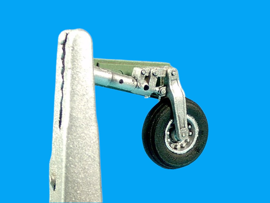
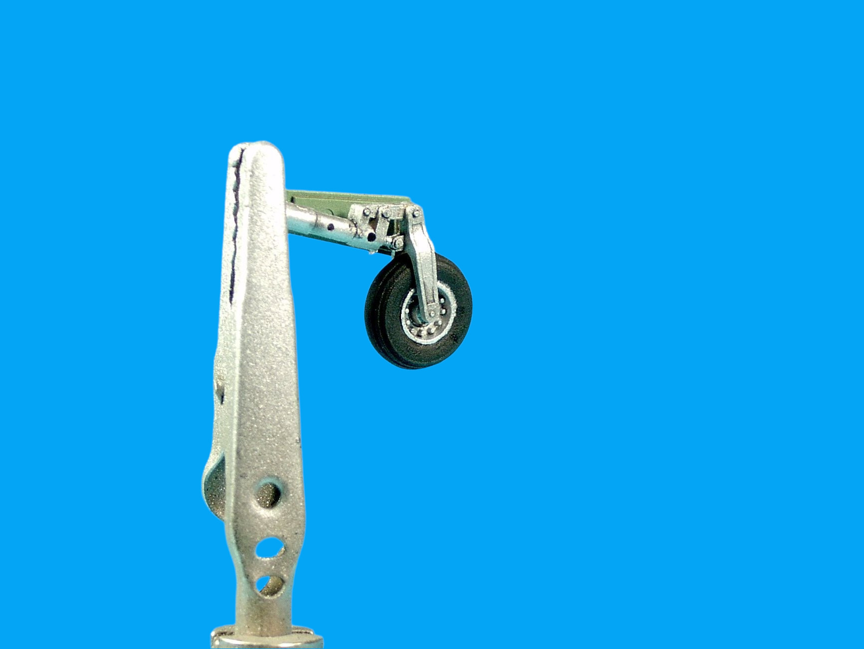

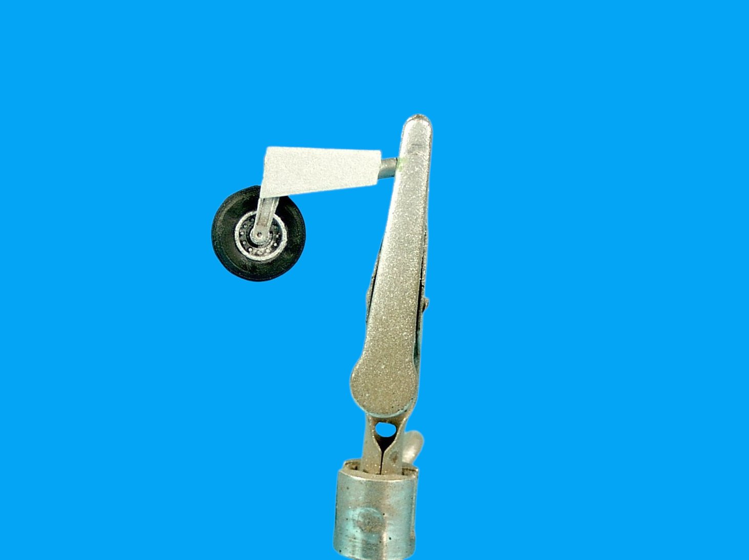

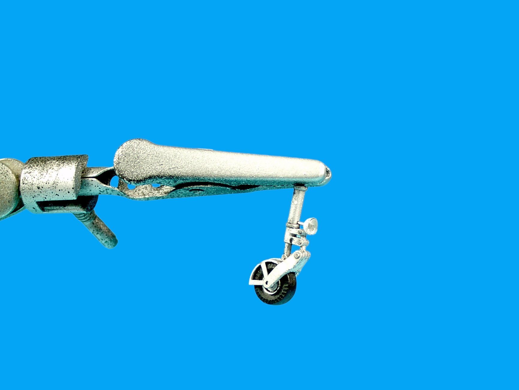

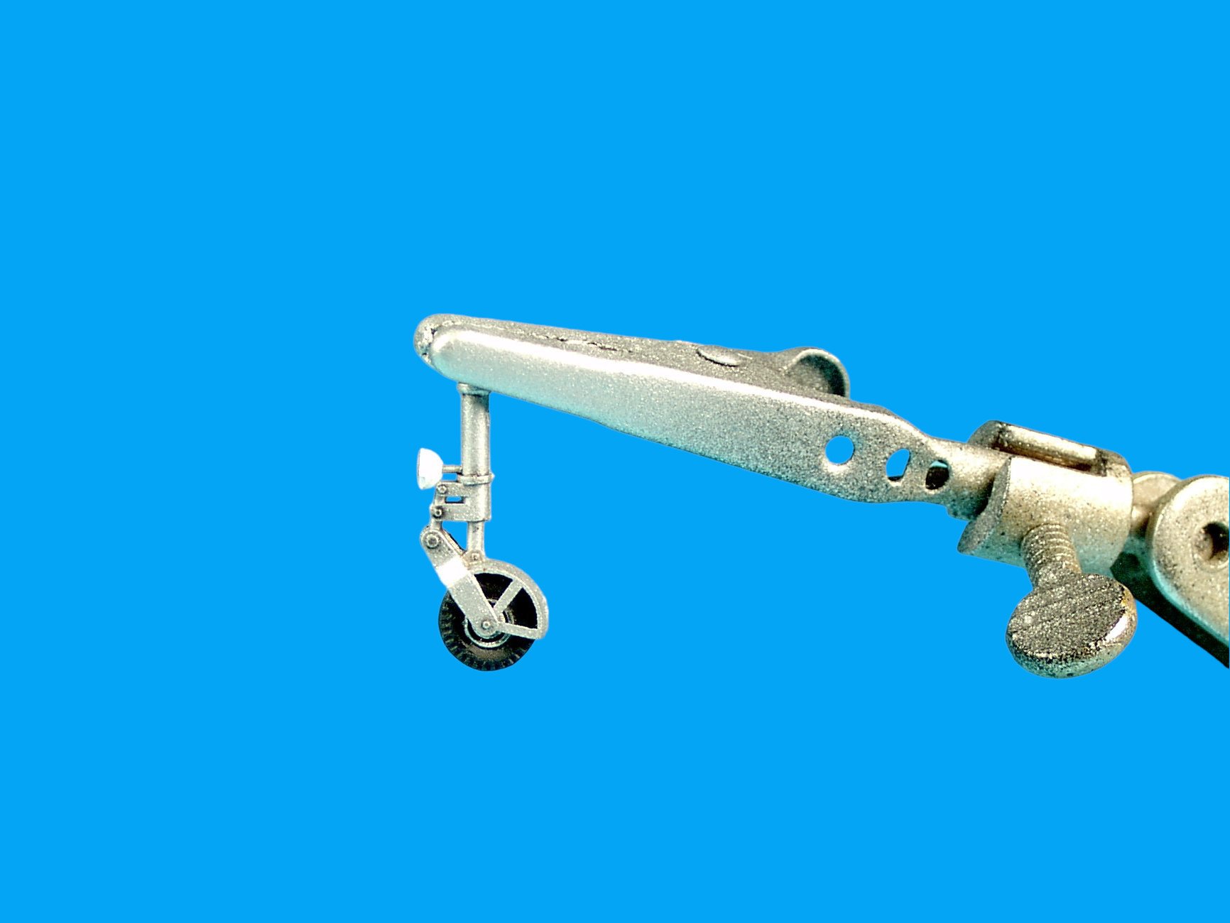


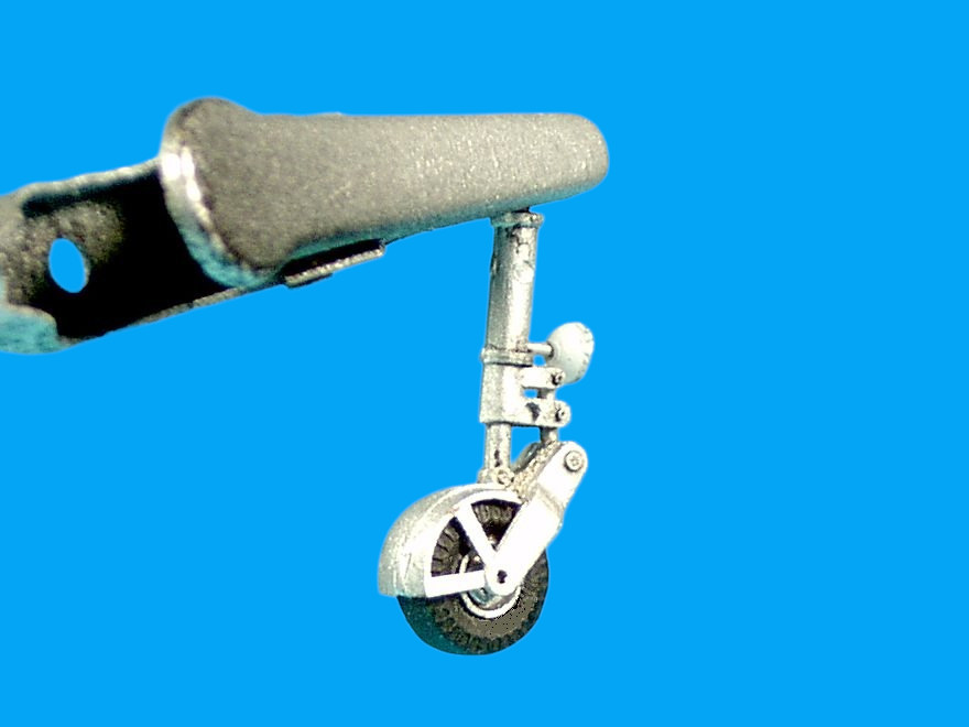
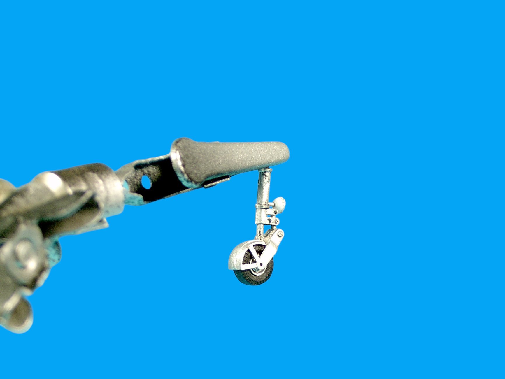
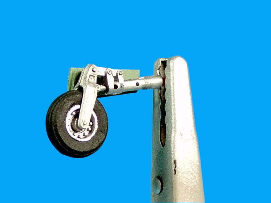

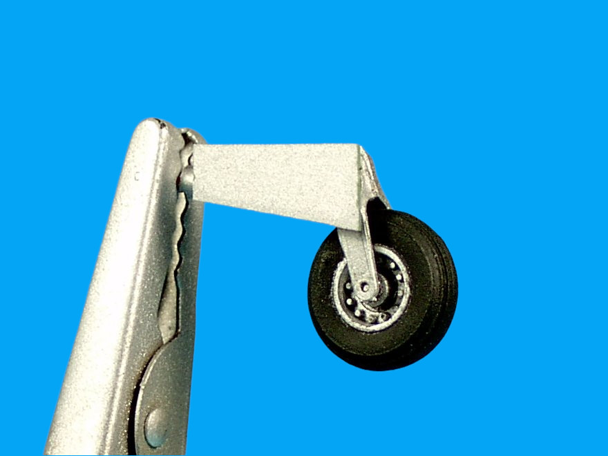

Notes: Note the engine exhaust side tube 17A is missing from the Italeri instructions, the part should be painted red and mounted on the starboard side just ahead of the engine exhaust (there's a slight indentation where the part is to be secured), see Esci Instructions Step 8 above. Do not mount the fin handles (parts 2 x 81B) in Step 5 of the Italeri instructions. Instructions to mount and paint a headlight on the landing gear under the nose (96C) is missing and the part is even grayed-out in the instructions, see Esci instructions Step 6 to mount. The landing gear doors are also upside down in the Italeri instructions (31A + 32A). I'm surprised at the amount of peeling I encountered with Modelmaster Acryl (the old Polly Scale), I think it had to with several things: the paint hadn't cured, the plastic probably wasn't as clean as I could have gotten it although peeling occurred everywhere I masked, and that you need a primer with these paints or at least apply two coats. I did notice where the paint cured one coat was in fact enough but again Polly Scale paints stuck to surfaces like glue, including resin surfaces, and in all the years using that paint I never once encountered peeling when masking which suggests the formula had been changed when Rustoelum took over. I painted on complex Italian WWII camo with those paints and because of the high-surface tension overspray was almost non-existent - they were great paints - what a shame. So why is this important? With older stampings panel lines fade and when you add one extra layer of paint it doesn't help. Also the thinner the paint the more realistic the finish. Note Italeri Instructions part 17A is for the red starboard-side exhaust tube. Use Italeri part 9A for the under side airbrake hydraulic cylinder with the top of the piston rod attached to the airbrake - see Esci Instructions Step 8 above. I wasn't able to determine if 468/68 was one of the early Macchi-built planes or the ones manufactured by Atlas, although the beacons suggest that this plane might have been built by Atlas. In the Italeri Instructions parts 10A and 12A are upside down and inverted, see Esci Instructions above Step 8 for correct mounting. These two parts are the bars that attach to the main struts and appear to have been present on some machines while missing on others, in any event the kit supplied parts are too long so I left them off as others have. The main landing gear struts fit exactly, there are no fit problems. The nose landing gear aperture is misaligned by about 1mm and seems likely to be a mould issue but the landing gear strut still fits fine. Another thing to note is that the moulds for the fuselage halves are well worn, for example the recessed panel lines are quiet shallow making rescribing difficult while the upper and lower wing moulds appear almost new with crisp detail. Once again, there are parts in the incorrect position in the Italeri Instructions Step 8, this time parts 29A and 30A should be on opposite sides. Also these parts should be mounted in the inside wheel well sitting on notches that should be deleted so that the doors sit deeper and the headlights fully exposed. I should also mention the gun pod chute for spent cases is on the wrong side of each pod although I couldn't tell with the limited photos of these guns if the pods or panels could be switched or interchanged, but because of the way the gun pods wrap around the wings its impossible to fix although it doesn't make a big difference. One final note, the wheels rotate beautifully with no wobble, so much so that my plane almost rolled off the table before I had a chance to photograph the completed model - you've been warned! Photos were taken using my old HP 720 Photosmart which still takes pretty good photos under the right lighting conditions and I actually prefer using it in these cases over my Google Pixel.


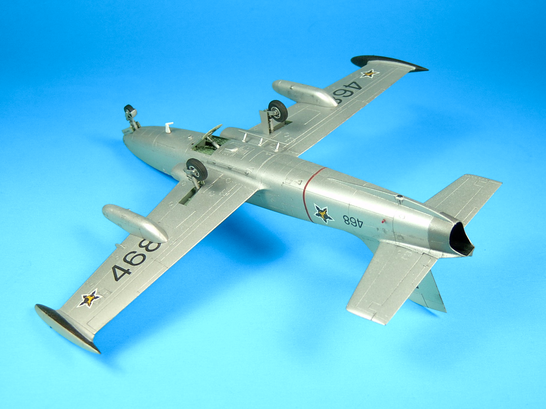
Final Assembly: Add the undercarriage beginning with the main landing gear and doors - there are no fit problems here and the struts snap into place. Add the gun pods and then the nose landing gear and doors. Note that the nose landing gear doors should sit partially inside the wheel well such that the front headlight is visible. There are four notches in this area that could/should be removed (during construction) so that the landing gear doors sit deeper, thus exposing the front head-light fully. Next add the red side-pipe from the engine exhaust on the starboard side. Add the second dorsal bulb behind the dorsal beacon and then add a bulb to the dorsal beacon. Install the canopy and its hydraulic cylinder (Please note: the horizontal bracket at the bottom of the canopy, and the canopy hydraulic cylinder both need to be scratch-built). The gunsight that comes with the kit is oversized and unrealistic, I replaced it with an unspecified Neomega part that fit exactly into that slot and looks right. Mount the windshield and the two pitot tubes ahead of the windshield.
What could I have done better? The ejector seats are removable so when I get some time I may go back and complete them with added detail such as the ejector seat handles and perhaps some coloring. The inner exterior wing-tip tanks are painted black around the contours of the tanks but were extended further inboard on SAAF MB-326M/Impala Mk.Is - my tanks are painted like Italian MB-326s, and although the SAAF received 40 MB-326Ms from Aermacchi, the Silver Falcons likely flew the Impala. The ventral antenna/fin could have been thinned (sanded down), it looks a little too thick, a PE part would have worked better here but otherwise its ok. The top of the rudder and fin of the Impala Mk.I was either a one or two tone gray, the gray I used was of the lighter variety, I should have used a darker shade for this plane. Other than that, the model is a geniune 1/48 SAAF MB-326M/Imapla Mk.I flown by the SAAF Silver Falcons aerobatic team coded 468/68. Conclusions: This kit took about 20 hrs to build, its a fast build and most time is spent in the cockpit, and with the canopy open, the cockpit details are conspicuous. The fit, ease of construction are noteworthy considering its a 43 yr old kit - the kit's main fault is the sparse cockpit that was typical for the day, but works ok if you plan to build this kit with the canopy in the closed position making this kit value-for-the-money (kind of). I'm surprised I don't see more builds of this kit considering how successful the MB-326 was commercially, its a beautiful plane, its widespread use, as well as its successful operational career that included combat and the sheer delight of flying the plane as reported by its pilots. This kit reminded me why so many people enjoy building old fashioned plastic kits with guide pins that help with quick, accurate assembly, as opposed to resin or vacuum formed kits or even short/limited run kits that require a delicate hand and much finessing. This kit went together well, there's little flashing and your time is spent building the kit as opposed to correcting it or sanding it, and with a pressing schedule like mine and the desire to just add a model to my collection that looked interesting, with an interesting history I much appreciated the convenience of this kit - there's allot of value here. I'd say this is one of the better kits I built in a while, except for the resin cockpit, the kit basically came together quickly and really put the fun back into the hobby for me, and while acknowledging that modern limited run kits finish nicely, these kits are often frustrating to build, fragile when complete and expensive, and prohibitive to kids that the hobby should be focusing on. This kit reminded me of the old venerable Hobbycraft kits, simple, good fit, your attention is focused on building a model and having fun! So here you have it, I wanted an MB-326 that was employed operationally, in combat with the air force that adopted it, and in an armed configuration and that's exactly what I got here - money and time well spent. This model is everything I had hoped it would be and some more. Recommended.
|
Aircraft: Aermacchi M.B.326K Manufacturer: Aeronautica Macchi S.p.A. Type: Trainer/Tactical Support Year: 1970 Engine: One Bristol Siddeley Viper 632 turbojet, 4,000 lb (1,814 kg) thrust Wingspan: 35ft 3in (10.74m) Length: 35ft 0 in (10.66 m) Height: 12ft 3in (3.72m) Weight: 12,000 lb (5,443 kg) (Loaded) Maximum Speed: 576mph (927 km/h) Ceiling: 50,000ft (15,000 m) Range: 932 miles (1,500 km) Armament: 2 30 mm cannon; 4,000lb (1,814kg) of bombs Crew: 1 |
|
|
|
|
|
|
|
|
|
|


|
|

|
|
|


|


|
|
|
|
March, 2025 STORMO! © 2025 |